

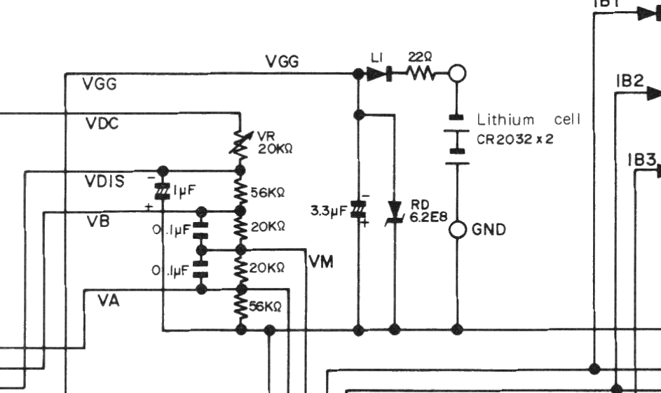
File:Sharp PC-1250 and PC-1251 power and LCD bias circuit (service manual).png

Summary
[edit | edit source]

The power and LCD bias part of the circuit diagram in Sharp's PC-1250/PC-1251 service manual (section 7): two CR2032 lithium cells feeding VGG through a 22 Ω resistor and diode L1, the 3.3 µF capacitor and RD6.2E8 zener across the supply, and the VR 20 kΩ contrast control with the resistor divider and capacitors that produce VDIS, VB, VM and VA. Rendered at 300 dpi from the scan and cropped.
Source
[edit | edit source]

File:Sharp PC-1251 Service Manual.pdf, PDF page 12. The scan came from Sharp Pocket Computers (sharppocketcomputers.com), retrieved 2026-10-21.
Author
[edit | edit source]

Sharp Corporation.
Licence
[edit | edit source]

Copyright Sharp Corporation. Hosted for preservation and repair reference, with the source cited.
File history
Click on a date/time to view the file as it appeared at that time.
| Date/Time | Thumbnail | Dimensions | User | Comment | |
|---|---|---|---|---|---|
| current | 19:00, 21 October 2026 | | 943 × 561 (32 KB) | Josh (talk | contribs) | Upload for Sharp PC-1245 and PC-1251 pages |
You cannot overwrite this file.
File usage
The following 2 pages use this file:
