

File:Sharp X68000 XVI power supply schematic (service manual).png

Summary
[edit | edit source]

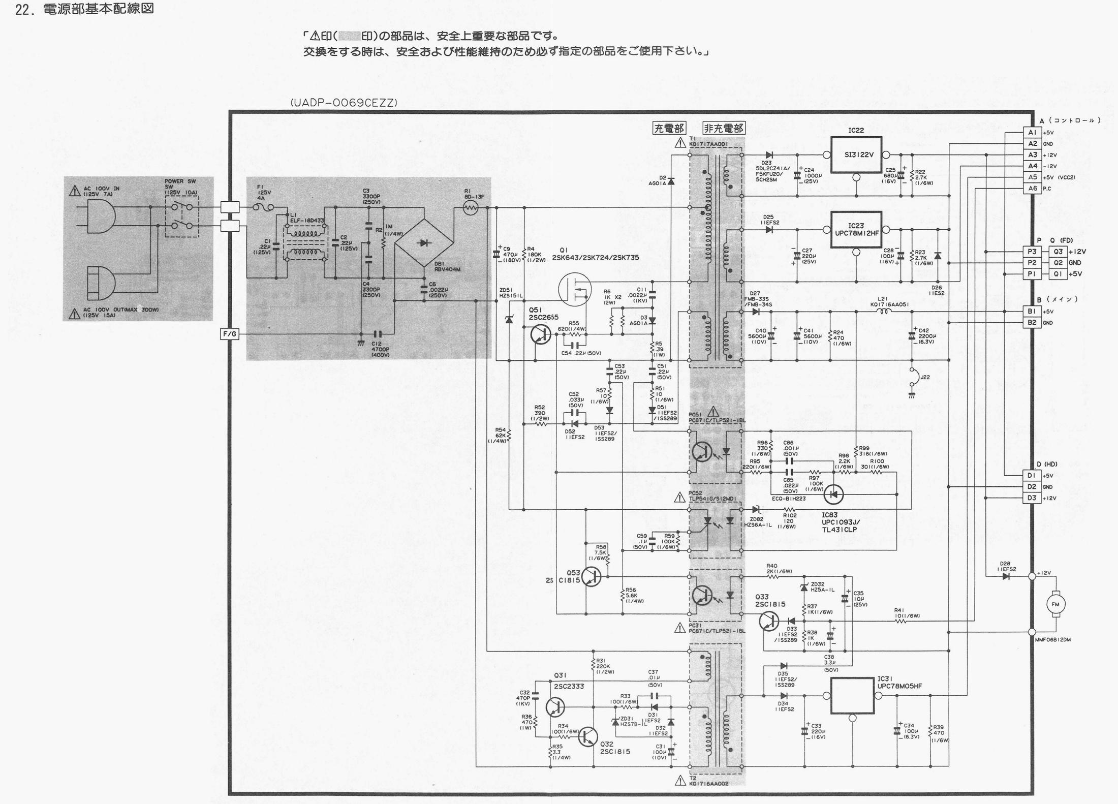
Sharp's power supply circuit diagram (電源部基本配線図, "power supply basic wiring diagram") for the X68000 XVI, board UADP-0069CEZZ, from service manual CZ-134, printed pages 97 to 98 (PDF page 85). Cropped to the drawing, converted to greyscale and reduced to 2,200 pixels wide. It shows the 100 V input and switched outlet, fuse F1 (125 V 4 A), bridge DB1, reservoir C9 (470 µF 180 V), switching transistor Q1, transformer T1 with the +12 V (IC22 SI3122V), −12 V (IC23 µPC78M12HF) and +5 V outputs, the T2 standby converter with IC31 (µPC78M05HF) for the +5 V VCC2 rail, the fan, and output connectors A (control board), B (main board), P and Q (floppy drives) and D (hard disk). The full manual is File:Sharp X68000 XVI Service Manual.pdf.
Source
[edit | edit source]

Cropped from Sharp service manual CZ-134, Internet Archive item CZ134X68000ServiceManual: https://archive.org/details/CZ134X68000ServiceManual (retrieved 2026-10-21)
Author
[edit | edit source]

Sharp Corporation
Licence
[edit | edit source]

Copyright Sharp Corporation. Sharp republished the manual free of charge for preservation and reference. Hosted here for preservation and repair reference, with the source cited.
File history
Click on a date/time to view the file as it appeared at that time.
| Date/Time | Thumbnail | Dimensions | User | Comment | |
|---|---|---|---|---|---|
| current | 19:39, 21 October 2026 | | 2,200 × 1,582 (978 KB) | Josh (talk | contribs) | Upload X68000 XVI power supply schematic crop |
You cannot overwrite this file.
