

File:Slide switch construction diagram.png
Summary
[edit | edit source]

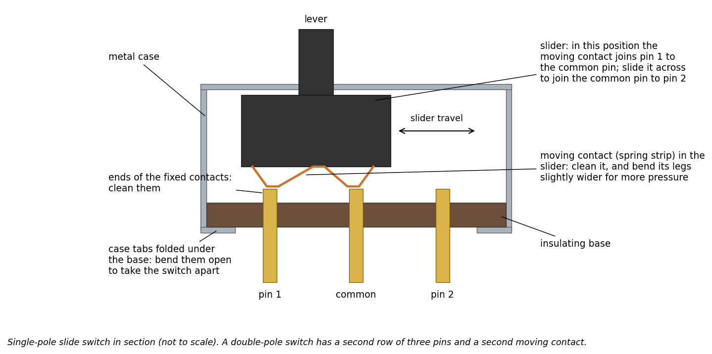
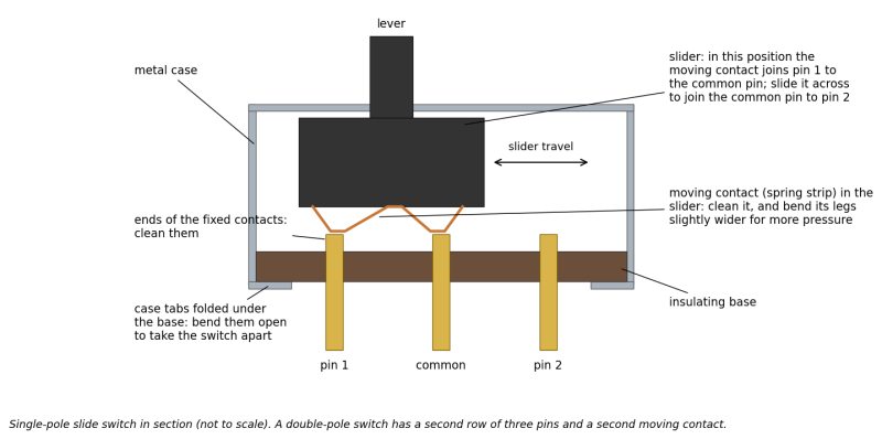
Cross-section diagram of a single-pole, two-position slide switch: the metal case with its tabs folded under the insulating base, the plastic slider and lever, the spring-strip moving contact carried in the slider, and the three fixed contacts (pin 1, common, pin 2). In the position shown the moving contact joins pin 1 to the common pin. Notes mark where to open the case, which surfaces to clean and that the moving contact's legs are bent slightly wider to restore contact pressure. Not to scale.
Source
[edit | edit source]

Drawn for this wiki in October 2026 from the switch repair described in Vintage Gaming and More, "Atari 2600 Switch Repair (Power and Reset/Select)", https://vintagegamingandmore.com/atari-switch-repair/ (retrieved 2026-10-25). Used on Switch and Potentiometer Repair.
Author
[edit | edit source]

RetroTechCollection wiki.
Licence
[edit | edit source]

Released under CC BY-SA 4.0 (https://creativecommons.org/licenses/by-sa/4.0/).
File history
Click on a date/time to view the file as it appeared at that time.
| Date/Time | Thumbnail | Dimensions | User | Comment | |
|---|---|---|---|---|---|
| current | 15:22, 25 October 2026 | | 1,438 × 716 (98 KB) | Josh (talk | contribs) | Upload diagram drawn for the repair-technique pages |
You cannot overwrite this file.
File usage
The following page uses this file:
