

File:Tandon TM100 logic board test points (manual figure 5-1).png

Summary
[edit | edit source]

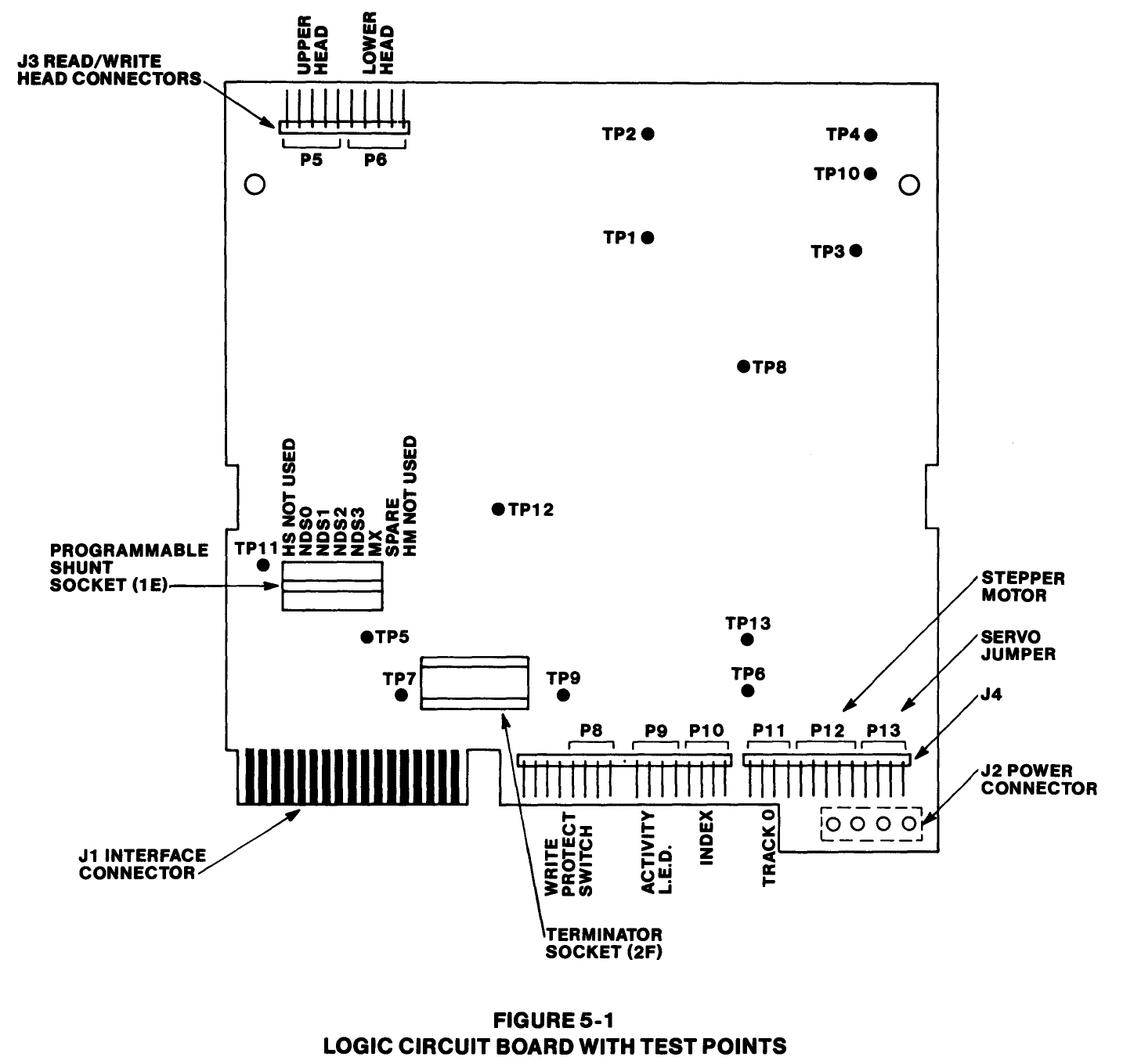
Figure 5-1 from Tandon's TM100 service manual, "Logic Circuit Board with Test Points": the TM100-1 / TM100-2 logic board with test points TP1 to TP13, the head connectors P5 and P6, connectors P8 to P13 (P11 is Track 0), the J1 interface connector, J2 power connector and the programmable shunt socket 1E. Rendered at 200 dpi and cropped.
Source
[edit | edit source]

Tandon Corporation, OEM Operating and Service Manual, TM100-1, TM100-2 Disk Drives, 48 Tracks Per Inch, 179022-001 Rev. B (1983), p. 5-2 (PDF page 44), hosted here as File:Tandon TM100-1 TM100-2 48TPI Operating and Service Manuals 1983.pdf.
Author
[edit | edit source]

Tandon Corporation
Licence
[edit | edit source]

Copyright Tandon Corporation, 1983. Not freely licensed. Reproduced for repair reference, with the source cited.
File history
Click on a date/time to view the file as it appeared at that time.
| Date/Time | Thumbnail | Dimensions | User | Comment | |
|---|---|---|---|---|---|
| current | 22:41, 25 October 2026 | | 1,434 × 1,359 (42 KB) | Josh (talk | contribs) | Upload for repair guide |
You cannot overwrite this file.
File usage
The following 4 pages use this file:
