

File:Tandy 102 main board (Service Manual Fig. 1-4).png

Summary
[edit | edit source]

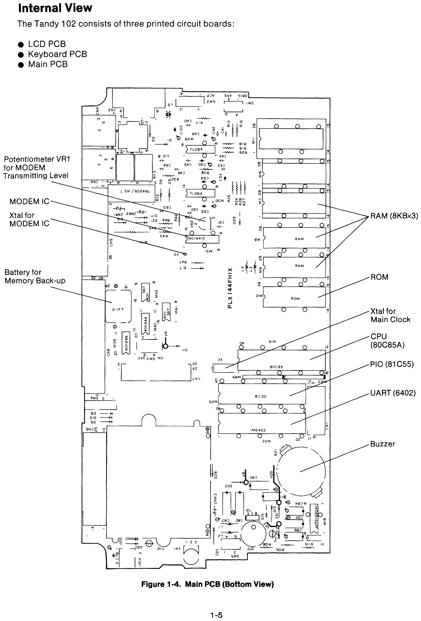
Figure 1-4, "Main PCB (Bottom View)", from Tandy's Service Manual for the Tandy 102 (catalogue number 26-3803), page 1-5. It shows the main board, marked PLX144FHIX, with the part references, the RAM sockets M6 to M9, the ROM sockets M11 and M12, the 80C85A, 81C55 and 6402, the memory backup battery (3-1FT) and the power section around the converter transformer OT2. The callout "Potentiometer VR1 for MODEM Transmitting Level" points to the part marked VR2 on the drawing; the parts list gives VR2 as the modem level control and VR1 as the contrast control. Rendered at 200 dpi.
Source
[edit | edit source]

File:Tandy 102 Service Manual (26-3803).pdf, PDF page 12; originally Internet Archive item manualzilla-id-7319716 (retrieved 2026-10-21).
Author
[edit | edit source]

Tandy Corporation (Radio Shack)
Licence
[edit | edit source]

Copyright Tandy Corporation. Hosted for preservation and repair reference, with the source cited.
File history
Click on a date/time to view the file as it appeared at that time.
| Date/Time | Thumbnail | Dimensions | User | Comment | |
|---|---|---|---|---|---|
| current | 22:47, 21 October 2026 | | 1,380 × 2,036 (90 KB) | Josh (talk | contribs) | Upload Tandy 102 main board for the Tandy 102 pages |
You cannot overwrite this file.
File usage
The following 2 pages use this file:
