

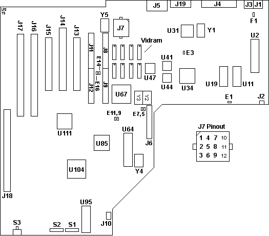
File:Tandy 5000 MC main logic board layout (Ardent Tool).png
Size of this preview: 525 × 460 pixels.
Original file (525 × 460 pixels, file size: 6 KB, MIME type: image/png)
Summary
[edit | edit source]

Layout sketch of the Tandy 5000 MC main logic board (Tandy part 8899061) showing the positions of the connectors J1 to J19, jumpers E1, E3, E5 to E16, DIP switches S1 and S2, reset switch S3, fuse F1, the main chips and crystals, and the pin numbering of the 12-pin power connector J7.
Source
[edit | edit source]

https://www.ardent-tool.com/Tandy/5000MC_Planar.gif (Ardent Tool of Capitalism, Tandy 5000 MC page; retrieved 2026-10-22). Converted from GIF to PNG.

Author
[edit | edit source]

Ardent Tool of Capitalism contributors
Licence
[edit | edit source]

No licence stated by the source. Used with credit for repair reference.
File history
Click on a date/time to view the file as it appeared at that time.
| Date/Time | Thumbnail | Dimensions | User | Comment | |
|---|---|---|---|---|---|
| current | 00:13, 22 October 2026 | | 525 × 460 (6 KB) | Josh (talk | contribs) | Upload: Tandy 5000 MC main logic board layout (Ardent Tool) |
You cannot overwrite this file.
File usage
The following page uses this file:
