

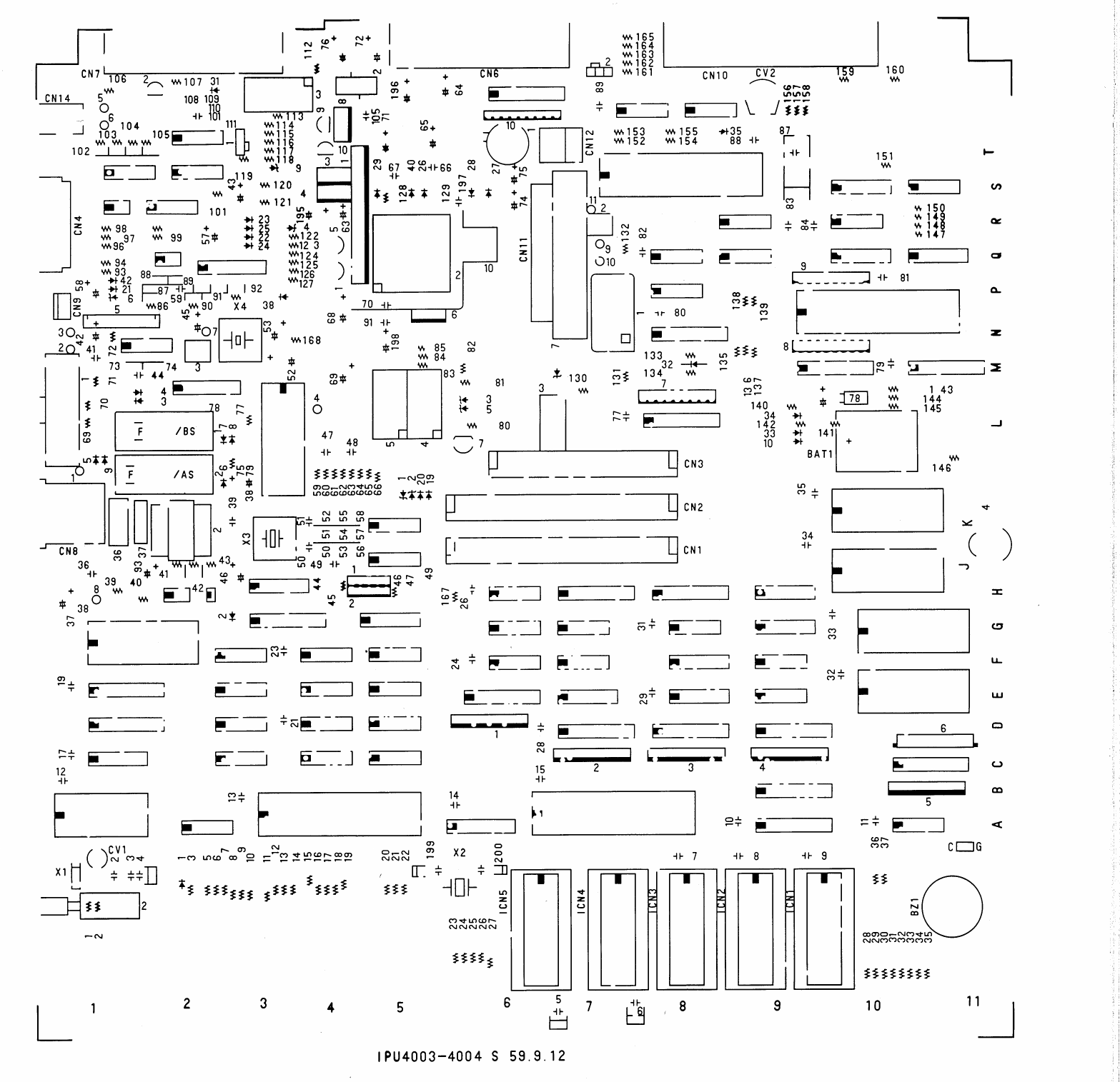
File:Tandy 600 main PCB OPMP silk-screen side (Service Manual section 9.1.1).png

Summary
[edit | edit source]

Silk-screen print side (top view) of the Tandy 600 main PCB, the OPMP board, from section 9.1.1 of the Tandy 600 Portable Computer Service Manual. It shows component reference numbers, the ROM sockets ICN1 to ICN5, the RAM card connectors CN1 to CN3, connectors CN4 to CN14, the backup battery BAT1, the buzzer BZ1, the trimmer capacitors CV1 and CV2, crystals X1 to X4, and a grid of columns 1 to 11 and rows A to T along the edges. The board legend reads IPU4003-4004 S 59.9.12.
Source
[edit | edit source]

File:Tandy 600 Service Manual (26-3901).pdf, PDF page 225 (printed page 193); original scan at https://archive.org/details/tandy_600_26-3901_servicemanual (retrieved 2026-10-22). Rendered at 200 dpi and cropped.
Author
[edit | edit source]

Tandy Corporation
Licence
[edit | edit source]

Copyright Tandy Corporation. Manufacturer's service drawing, hosted for repair reference with the source cited.
File history
Click on a date/time to view the file as it appeared at that time.
| Date/Time | Thumbnail | Dimensions | User | Comment | |
|---|---|---|---|---|---|
| current | 01:13, 22 October 2026 | | 1,567 × 1,515 (185 KB) | Josh (talk | contribs) | Upload: Tandy 600 main PCB OPMP silk-screen side (Service Manual section 9.1.1) |
You cannot overwrite this file.
File usage
The following 4 pages use this file:
