

File:Victor HC-90 fan motor board EA-8020A schematic.png

Summary
[edit | edit source]

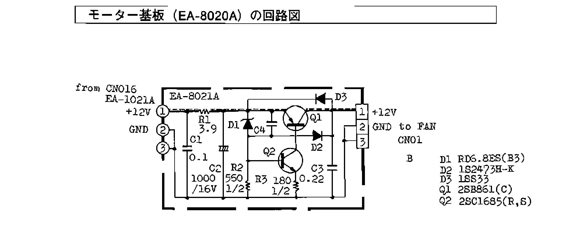
Circuit of the fan motor board (EA-8020A, board marked EA-8021A) of the Victor HC-90 and HC-95: +12 V and ground in from CN016 on board EA-1021A; R1 3.9 Ω; C1 0.1 µF; C2 1000 µF 16 V; zener D1 RD6.8ES(B3); R2 560 Ω 1/2 W; R3 180 Ω 1/2 W; C3 0.22 µF; C4; transistors Q1 2SB861(C) and Q2 2SC1685(R,S); diodes D2 1S2473H-K and D3 1SS33; output to the fan on CN01.
Source
[edit | edit source]

Cropped from File:Victor HC-90 HC-95 schematics and parts changes.pdf, PDF page 4 (embedded image extracted and inverted to black on white) on 2026-10-21.
Author
[edit | edit source]

Victor Company of Japan.
Licence
[edit | edit source]

Copyright Victor Company of Japan. Hosted for repair reference, with the source cited.
File history
Click on a date/time to view the file as it appeared at that time.
| Date/Time | Thumbnail | Dimensions | User | Comment | |
|---|---|---|---|---|---|
| current | 13:11, 21 October 2026 | | 1,935 × 814 (18 KB) | Josh (talk | contribs) | Victor HC-90 documentation and images |
You cannot overwrite this file.
File usage
There are no pages that use this file.
