

Commodore VIC-20
 | |
 | |
| Commodore VIC-20 | |
| Specifications | |
|---|---|
| Manufacturer | Commodore Business Machines |
| Type | Home computer |
| Released | 1981[1] |
| Discontinued | 1985[1] |
| Intro price | US$299.95 (1981)[1] |
| CPU | MOS Technology 6502 at 1.108 MHz (PAL) or 1.0227 MHz (NTSC) |
| Memory | 5 KB RAM (3,583 bytes free to BASIC), expandable to 40 KB |
| Storage | Datasette cassette recorder; VIC-1540/1541 5.25-inch disk drive |
| Display | 176 × 184 pixels, 22 × 23 text characters |
| Sound | Three tone generators and one noise generator in the VIC |
| Graphics | MOS 6560 (NTSC) or 6561 (PAL) VIC |
| Power | 9 V AC only (early boards) or +5 V DC and 9 V AC (VIC-20CR) |
| Dimensions | 403 × 204 × 72 mm |
| Weight | About 1.8 kg |
| OS / Firmware | Commodore BASIC 2.0 in ROM |
| Predecessor | Commodore PET 4000 Series |
| Successor | Commodore 64 |
| Model no. | VIC-1001 (Japan), VIC-20, VC-20 (German-speaking countries) |
The Commodore VIC-20 is Commodore Business Machines' first colour home computer, produced from 1981 to 1985. It was sold as the VIC-1001 in Japan and the VC-20 in German-speaking countries, and was the first computer to sell more than one million units.[1]
Commodore's parts lists and schematics for the machine are in the Commodore VIC-20 Technical Manual and the hosted Version E logic schematic.[2][3]
Architecture and processor
[edit | edit source]The CPU is a MOS Technology 6502 at 1.108 MHz on PAL machines and 1.0227 MHz on NTSC machines, divided down from the video crystal.
The crystal is 14.31818 MHz on NTSC machines (Commodore part 900558-01 / 251042-01) and 8.867236 MHz on PAL machines (900562-01 / 251042-02).[2] The 17.734472 MHz crystal belongs to the PAL C64, not the VIC-20.
Memory
[edit | edit source]The VIC-20 has 5 KB of RAM, of which 3,583 bytes are free to BASIC. Memory cartridges expand it to a maximum of 40 KB, of which up to 27.5 KB is usable by BASIC.[1]
Display and graphics
[edit | edit source]The VIC, a 6560 on NTSC machines and a 6561 on PAL, gives 22 columns by 23 rows of text and 176 × 184 pixels through programmable characters. Characters and border take 8 colours and the background 16.[1] The VIC also contains the sound generators and the two A/D converters for the paddles.[4]
The VIC's VDD is pin 40, connected to +5 V with a 0.1 µF decoupler; VSS is pin 20.[3][2]
Sound
[edit | edit source]Three tone generators and one white-noise generator, all inside the VIC chip.[1]
Power
[edit | edit source]The two board families are supplied differently, and the power supplies are not interchangeable.
| Assembly | PC board | External tell | On-board 5 V regulator |
|---|---|---|---|
| 324003 | 324002, revisions C, D, E, F | 2-pin power connector | Yes, VR1 |
| 250403 (VIC-20CR) | 251040 | 7-pin DIN power connector | None |
Commodore's parts list for the 324003 assembly is titled VIC-1001 PCB ASSY; the board is common to the VIC-1001 and the early VIC-20. The list gives quantities only for USA and NTSC versions (-02, -05 and -09); its lines for the PAL 6561 and the PAL crystal have no quantity in those versions.[2]
- On an early (324003) board the external supply provides 9 V AC only. The AC comes in at J1, through fuse F1 (3 A slow-blow, Commodore 903559-04) and switch SW1, to a bridge rectifier, a 4700 µF 16 V reservoir (C39 in Commodore's 324003 parts list, C1 on the Version E schematic), and then to VR1.[3][2]
- On a VIC-20CR (250403) board the external supply provides both a regulated +5 V DC rail and 9 V AC, and the board has no voltage regulator. The on-board bridge and its 2200 µF reservoir make the 9 V unregulated rail for the cassette motor drive; the video output stage runs from +5 V. F1 here is 1 A slow-blow (903558-11).[2]
VR1 is not a 7805. Commodore's parts list gives it as an LM323 (part 901528-01); the Version E schematic marks it SI-3554M. Read the part number off your own regulator before ordering a replacement.[2][3]
There is no +12 V rail in a VIC-20: the VIC runs from +5 V, and the schematic shows only +5 V and the 9 V unregulated rail.[3][2]
A VIC-20CR takes its regulated +5 V straight from the external supply, so the over-voltage hazard of the Commodore 64 supply applies to it too; see Commodore 64 Power-Supply Protector (C64 Saver).
Input, output and expansion
[edit | edit source]- Cartridge (expansion) port: software and memory expansion
- User port: modems and user hardware; not compatible with the C64's user port
- Serial port: Commodore serial bus, for drives and printers
- One control port, 9-pin, for a joystick, light pen or paddles[1]
- Cassette port: Datasette
- Audio/video and RF output
Motherboard and schematic
[edit | edit source]| Logic board | Schematic diagrams |
|---|---|
 |
 |
Maintenance
[edit | edit source]For procedures see Commodore VIC-20 General Maintenance, Commodore VIC-20 Troubleshooting Guide and Commodore VIC-20 Capacitor Replacement Guide.
Documentation hosted here
[edit | edit source]- Commodore VIC-20 Technical Manual
- VIC-20 Schematic, Main Logic Version E
- VIC-1001 schematic
- Commodore Test Cartridge Index
Gallery
[edit | edit source]-
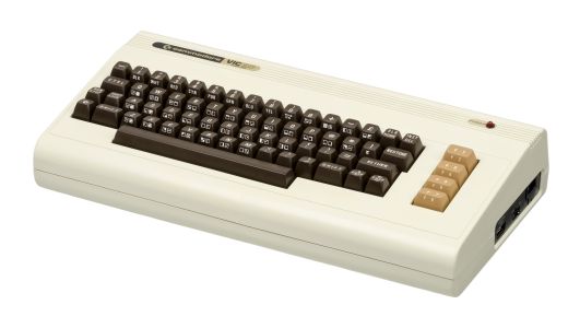 Front view of the Commodore VIC-20
-
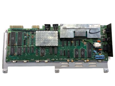 Internal motherboard layout
Related pages
[edit | edit source]- Commodore 64
- Commodore PET 2001
- Commodore VIC-20 General Maintenance
- Commodore VIC-20 Troubleshooting Guide
- Commodore VIC-20 Capacitor Replacement Guide
References
[edit | edit source]- ↑ 1.0 1.1 1.2 1.3 1.4 1.5 1.6 1.7 VIC-20—link(accessed 2026-10-01) Produced 1981 to 1985; US$299.95 (1,000 DM); 5 KB RAM with 3583 bytes free to BASIC, expandable to 40 KB; 22 × 23 text, 176 × 184 pixels; 403 × 204 × 72 mm, about 1800 g; marketed as the VC-20 in German-speaking countries and the VIC-1001 in Japan; first computer to sell more than one million units.
- ↑ 2.0 2.1 2.2 2.3 2.4 2.5 2.6 2.7 Commodore Business Machines, Technical Manual, Model VIC-20, PN 990440, hosted at Commodore VIC-20 Technical Manual. Contains Commodore's parts list for PCB assembly 324003 (titled VIC-1001 PCB ASSY, PC board 324002 revisions C-F), the parts list for the VIC-20CR assembly 250403 (PC board 251040), the three-sheet VIC-20CR schematic 251027-01 Rev C, the crystal part numbers, and the fuse ratings for both boards.
- ↑ 3.0 3.1 3.2 3.3 3.4 Commodore Business Machines, VIC-20 Schematic Main Logic Version E, © 1980, hosted as File:Commodore VIC-20 Schematic (Version E).pdf. Single-sheet logic schematic: power jack J1, switch SW1, fuse F1, bridge rectifier and regulator VR1 (marked SI-3554M), the 6560 VIC and the 6502A pin assignments.
- ↑ VIC—link(accessed 2026-10-01) VIC-I features: on-chip sound system with white-noise generator and two 8-bit A/D converters; 6560 for NTSC, 6561 for PAL.