

File:Atari 1010S motor control circuit (FSM schematic).png
Summary
[edit | edit source]

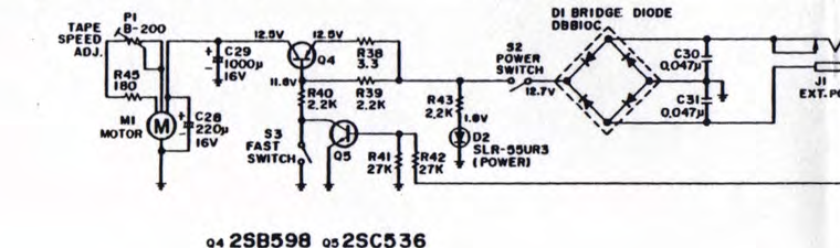
Motor and power section of Atari's 1010S schematic ("1010S Schematic Page 2"): bridge rectifier D1, power switch S2 and LED D2, motor control transistors Q4 (2SB598) and Q5 (2SC536), fast switch S3, C29 1000 µF 16 V, motor M1 with C28 220 µF 16 V, R45 and the tape speed control P1. Rotated to read horizontally. Cropped from the field service manual.
Source
[edit | edit source]

Atari, Inc., 1010 Cassette Recorder Field Service Manual, FD100223 Rev. 02, September 1983, hosted here as File:Atari 1010 Cassette Recorder Field Service Manual FD100223 Rev 02.pdf, fold-out schematic, PDF page 10.
Author
[edit | edit source]

Atari, Inc.
Licence
[edit | edit source]

Copyright Atari, Inc. Hosted for preservation and repair reference, with the source cited.
File history
Click on a date/time to view the file as it appeared at that time.
| Date/Time | Thumbnail | Dimensions | User | Comment | |
|---|---|---|---|---|---|
| current | 16:28, 25 October 2026 | | 760 × 225 (197 KB) | Josh (talk | contribs) | Crop of Atari 1010 FSM figure for repair guide |
You cannot overwrite this file.
File usage
The following page uses this file:
