

File:Atari 1020 board silkscreen (field service manual figure 2-1).png

Summary
[edit | edit source]

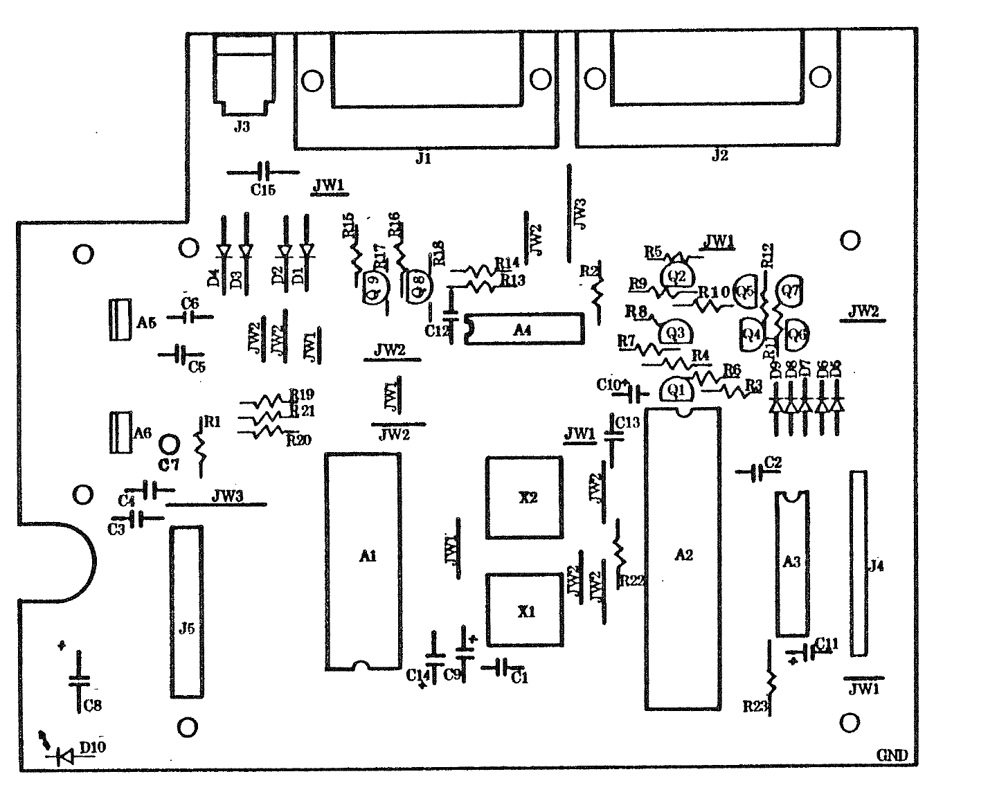
Component layout of the Atari 1020 Color Printer's main board, figure 2-1 ("1020 Color Printer Silkscreen") of Atari's 1020 Color Printer Field Service Manual (FD100288 Rev. 01, August 1983), page 2-3. It shows the positions of A1 to A6, Q1 to Q9, D1 to D10, X1 and X2, the capacitors and resistors, and connectors J1 to J5. The figure is printed sideways in the manual and has been rotated; light bleed-through from the reverse of the page has been removed.
Source
[edit | edit source]

Cropped and rotated from page 2-3 (PDF page 25) of File:Atari 1020 Color Printer Field Service Manual FD100288 Rev 01.pdf, rendered at 200 dpi.
Author
[edit | edit source]

Atari, Inc.
Licence
[edit | edit source]

Copyright Atari, Inc. Hosted for preservation and repair reference, with the source cited.
File history
Click on a date/time to view the file as it appeared at that time.
| Date/Time | Thumbnail | Dimensions | User | Comment | |
|---|---|---|---|---|---|
| current | 16:29, 25 October 2026 | | 1,440 × 1,170 (73 KB) | Josh (talk | contribs) | Atari 1020 field service manual figure, for the pen solenoid circuit repair guide |
You cannot overwrite this file.
File usage
The following page uses this file:
