

File:Atari 1025 base unit exploded view (field service manual figure 4-4).png

Summary
[edit | edit source]

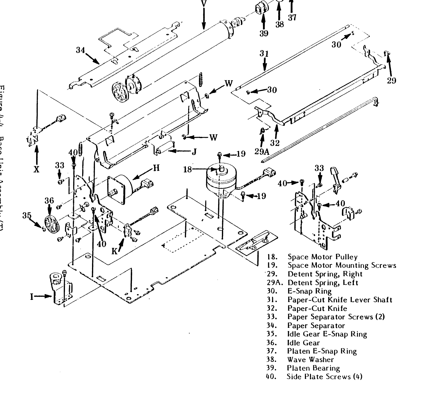
Figure 4-4 (Base Unit Assembly) of Atari's 1025 Printer Field Service Manual (FD100290 Rev. 01, June 1983), page 4-17, with its key: space motor pulley (18), space motor mounting screws (19), detent springs (29, 29A), paper-cut knife and shaft (30-32), paper separator and screws (33, 34), idle gear and E-ring (35, 36), platen E-ring, wave washer and bearing (37-39) and side plate screws (40). The figure is printed sideways in the manual and has been rotated; light bleed-through from the reverse of the page has been removed.
Source
[edit | edit source]

Cropped and rotated from page 4-17 (PDF page 47) of File:Atari 1025 Printer Field Service Manual FD100290 Rev 01.pdf, rendered at 200 dpi.
Author
[edit | edit source]

Atari, Inc.
Licence
[edit | edit source]

Copyright Atari, Inc. Hosted for preservation and repair reference, with the source cited.
File history
Click on a date/time to view the file as it appeared at that time.
| Date/Time | Thumbnail | Dimensions | User | Comment | |
|---|---|---|---|---|---|
| current | 17:01, 25 October 2026 | | 1,480 × 1,390 (101 KB) | Josh (talk | contribs) | Figure for an Atari 1025 repair guide |
You cannot overwrite this file.
File usage
The following page uses this file:
