

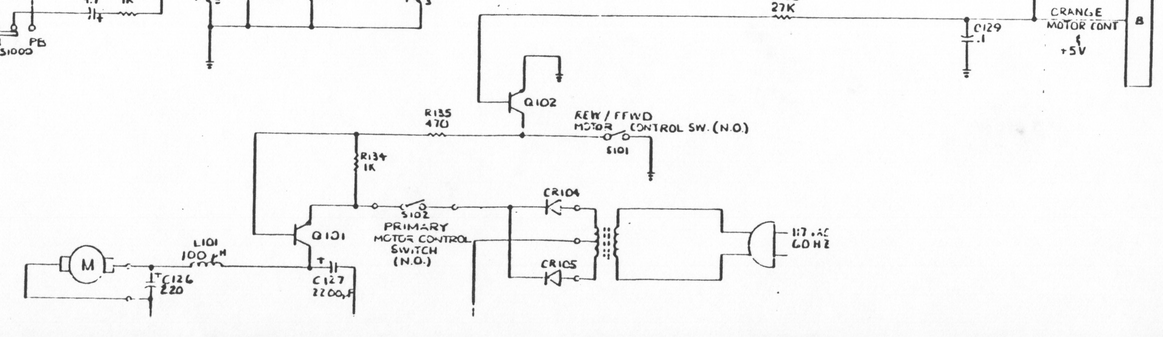
File:Atari 410 motor control circuit (FSM figure 7-1).png

Summary
[edit | edit source]

Motor and power section of Atari's figure 7-1, "410 Differences", the Transtek 410 schematic: the mains transformer and rectifiers CR104 and CR105, the primary motor control switch S102, Q101 with R134, Q102 driven from SIO pin 8 (motor control) through R136 27 kΩ, the REW/FFWD motor control switch S101, C127 2200 µF, L101 100 µH, C126 220 µF and the motor. Cropped and rotated to read horizontally.
Source
[edit | edit source]

Atari, Inc., 410 Program Cassette Recorder Field Service Manual, FD100004, May 1982, figure 7-1 (p. 7-1), hosted here as File:Atari 410 Program Cassette Recorder Field Service Manual FD100004.pdf. The whole figure is File:Atari 410 schematic (field service manual figure 7-1).png.

Author
[edit | edit source]

Atari, Inc.
Licence
[edit | edit source]

Copyright Atari, Inc. Hosted for preservation and repair reference, with the source cited.
File history
Click on a date/time to view the file as it appeared at that time.
| Date/Time | Thumbnail | Dimensions | User | Comment | |
|---|---|---|---|---|---|
| current | 16:52, 25 October 2026 | | 1,163 × 337 (253 KB) | Josh (talk | contribs) | Crop of Atari 410 FSM schematic for repair guide |
You cannot overwrite this file.
File usage
The following page uses this file:
