

File:Atari 520ST MIDI ports (schematic C070231 sheet 1).png

Summary
[edit | edit source]

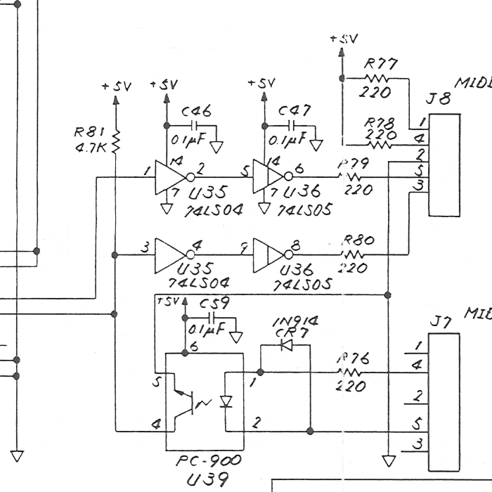
Crop of Atari's 520ST/260ST schematic, drawing C070231 revision M, sheet 1: the MIDI ports. MIDI OUT (J8 pins 4 and 5) is driven from the ACIA's transmit output through U35 (74LS04) pins 1–2 and U36 (74LS05) pins 5–6 and R79 (220 Ω), with R78 (220 Ω) to +5 V. MIDI IN (J7 pins 4 and 5) drives the opto-coupler U39 (PC-900) through R76 (220 Ω), with the protection diode CR7 (1N914); U39's output, pulled up by R81 (4.7 kΩ), goes to the ACIA and, through U35 pins 3–4, U36 pins 9–8 and R80 (220 Ω), to the THRU contacts on J8 pins 3 and 1 (R77, 220 Ω, to +5 V). Cropped from File:Atari 520ST Schematic C070231.pdf; see Atari 520ST Schematic (C070231).
Source
[edit | edit source]

File:Atari 520ST Schematic C070231.pdf (rendered 2026-10-25).
Author
[edit | edit source]

Atari (Japan) Corporation.
Licence
[edit | edit source]

Copyright Atari Corporation. Hosted for preservation and repair reference, with the source cited.
File history
Click on a date/time to view the file as it appeared at that time.
| Date/Time | Thumbnail | Dimensions | User | Comment | |
|---|---|---|---|---|---|
| current | 11:22, 25 October 2026 | | 700 × 700 (80 KB) | Josh (talk | contribs) | Crop of Atari 520ST schematic C070231 for MIDI repair guide |
You cannot overwrite this file.
File usage
The following page uses this file:
