

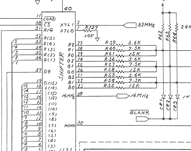
File:Atari 520ST Shifter colour outputs (schematic C070231 sheet 2).png

Summary
[edit | edit source]

Crop of Atari's 520ST/260ST schematic, drawing C070231 revision M, sheet 2: the video Shifter U31 with its red, green and blue outputs R0–R2, G0–G2 and B0–B2 (pins 21–29), each colour summed through 3.6 kΩ, 7.5 kΩ and 15 kΩ resistors (R53–R61), the pull-ups R62–R64, the BLANK clamp diodes CR1–CR3, the MONO output on pin 30, the 32 MHz clock input on pin 2 and the 16 MHz output on pin 39. Cropped from File:Atari 520ST Schematic C070231.pdf; see Atari 520ST Schematic (C070231).
Source
[edit | edit source]

File:Atari 520ST Schematic C070231.pdf (rendered 2026-10-25).
Author
[edit | edit source]

Atari (Japan) Corporation.
Licence
[edit | edit source]

Copyright Atari Corporation. Hosted for preservation and repair reference, with the source cited.
File history
Click on a date/time to view the file as it appeared at that time.
| Date/Time | Thumbnail | Dimensions | User | Comment | |
|---|---|---|---|---|---|
| current | 11:02, 25 October 2026 | | 800 × 633 (98 KB) | Josh (talk | contribs) | Crop of Atari 520ST schematic C070231 for video repair guide |
You cannot overwrite this file.
File usage
The following page uses this file:
