

File:Atari 520ST power supply schematic (SAMS Computerfacts CSCS12).png

Summary
[edit | edit source]

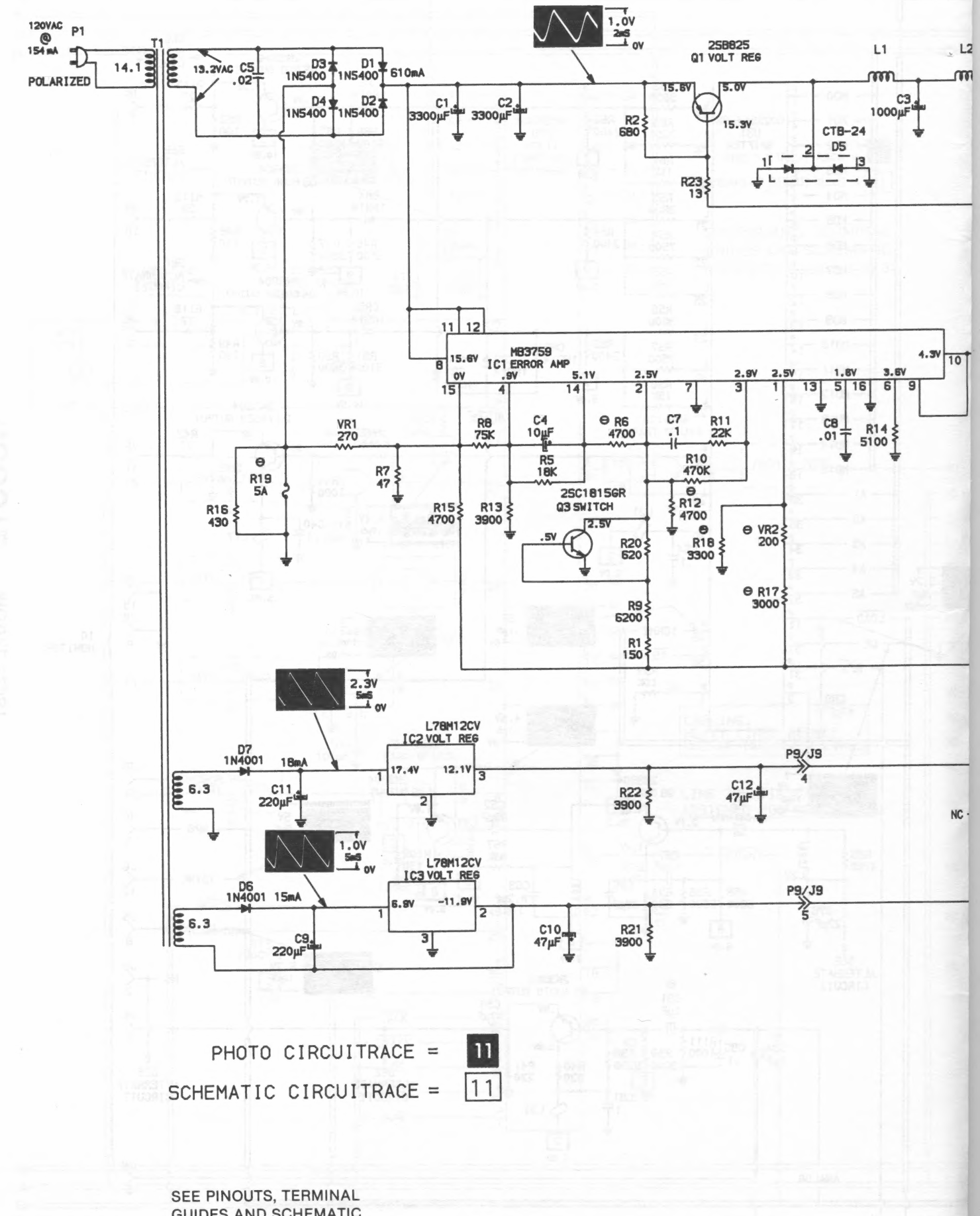
SAMS's schematic of the external power supply of a US Atari 520ST (120 V AC input), with measured voltages and waveforms: transformer T1, bridge D1–D4 (1N5400), reservoirs C1 and C2 (3300 µF), the +5 V regulator built from Q1 (2SB825), L1, D5 (CTB-24) and the controller IC1 (MB3759), the fuse R19, and the +12 V and −12 V regulators IC2 and IC3 fed through D7 and D6 from separate transformer windings. The right-hand edge of the printed page is cut off in the scan. From SAMS Computerfacts CSCS12: Atari Model 520ST (Howard W. Sams & Co., June 1986, ISBN 0-672-08974-2), printed page 6 (PDF page 8).
Source
[edit | edit source]

Internet Archive, item SAMSComputerfactsCSCS12Atari520ST, printed page 6 (PDF page 8) (retrieved 2026-10-25).
Author
[edit | edit source]

Howard W. Sams & Co.
Licence
[edit | edit source]

Copyright Howard W. Sams & Co., 1986. Used with credit for repair reference; not freely licensed.
File history
Click on a date/time to view the file as it appeared at that time.
| Date/Time | Thumbnail | Dimensions | User | Comment | |
|---|---|---|---|---|---|
| current | 10:58, 25 October 2026 | | 1,480 × 1,835 (577 KB) | Josh (talk | contribs) | Upload SAMS Computerfacts figure for Atari 520ST repair guide |
You cannot overwrite this file.
File usage
The following page uses this file:
