

File:Atari 520ST reset circuit (schematic C070231 sheet 2).png

Summary
[edit | edit source]

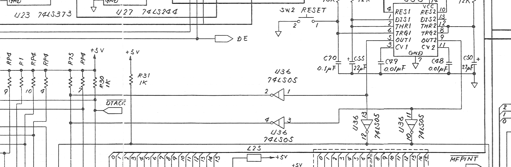
Crop of Atari's 520ST/260ST schematic, drawing C070231 revision M, sheet 2: the reset circuit. U37 is a 556 dual timer. One half, with R83 (12 kΩ), C50 (22 µF) and C48 (0.01 µF), times the reset at power-on; the other, triggered by the reset button SW2 with R93 (10 kΩ) and C70 (0.1 µF), times it with R82 (12 kΩ), C55 (22 µF) and C49 (0.01 µF). The outputs (pins 5 and 9) drive the open-collector inverters of U36 (74LS05), which pull the processor's reset lines low against the pull-ups R31 and R75. Cropped from File:Atari 520ST Schematic C070231.pdf; see Atari 520ST Schematic (C070231).
Source
[edit | edit source]

File:Atari 520ST Schematic C070231.pdf (rendered 2026-10-25).
Author
[edit | edit source]

Atari (Japan) Corporation.
Licence
[edit | edit source]

Copyright Atari Corporation. Hosted for preservation and repair reference, with the source cited.
File history
Click on a date/time to view the file as it appeared at that time.
| Date/Time | Thumbnail | Dimensions | User | Comment | |
|---|---|---|---|---|---|
| current | 11:07, 25 October 2026 | | 1,633 × 534 (145 KB) | Josh (talk | contribs) | Crop of Atari 520ST schematic C070231 for reset repair guide |
You cannot overwrite this file.
File usage
The following page uses this file:
