

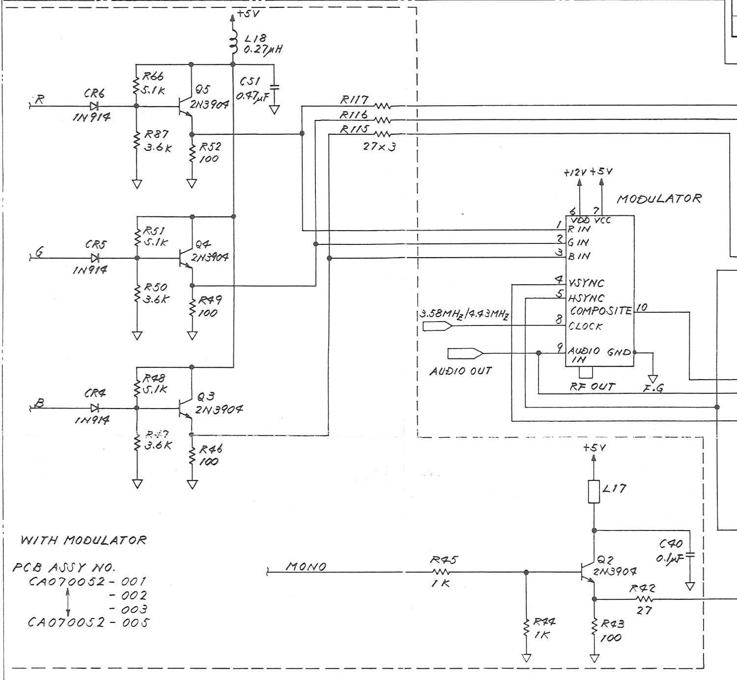
File:Atari 520ST video output buffers (schematic C070231 sheet 3).png

Summary
[edit | edit source]

Crop of Atari's 520ST/260ST schematic, drawing C070231 revision M, sheet 3, assembly with modulator: the emitter-follower video buffers Q5 (red), Q4 (green) and Q3 (blue), 2N3904 transistors fed through the diodes CR6, CR5 and CR4 with their bias resistors, the emitter resistors and the 27 Ω series resistors R117, R116 and R115 to the monitor socket and the modulator, the collector supply through L18, and the monochrome buffer Q2 with R45, R44, R43 and R42. Cropped from File:Atari 520ST Schematic C070231.pdf; see Atari 520ST Schematic (C070231).
Source
[edit | edit source]

File:Atari 520ST Schematic C070231.pdf (rendered 2026-10-25).
Author
[edit | edit source]

Atari (Japan) Corporation.
Licence
[edit | edit source]

Copyright Atari Corporation. Hosted for preservation and repair reference, with the source cited.
File history
Click on a date/time to view the file as it appeared at that time.
| Date/Time | Thumbnail | Dimensions | User | Comment | |
|---|---|---|---|---|---|
| current | 11:02, 25 October 2026 | | 1,500 × 1,383 (181 KB) | Josh (talk | contribs) | Crop of Atari 520ST schematic C070231 for video repair guide |
You cannot overwrite this file.
File usage
The following page uses this file:
