

File:Atari CX40 joystick schematic (2600 field service manual figure 7-2).png

Summary
[edit | edit source]

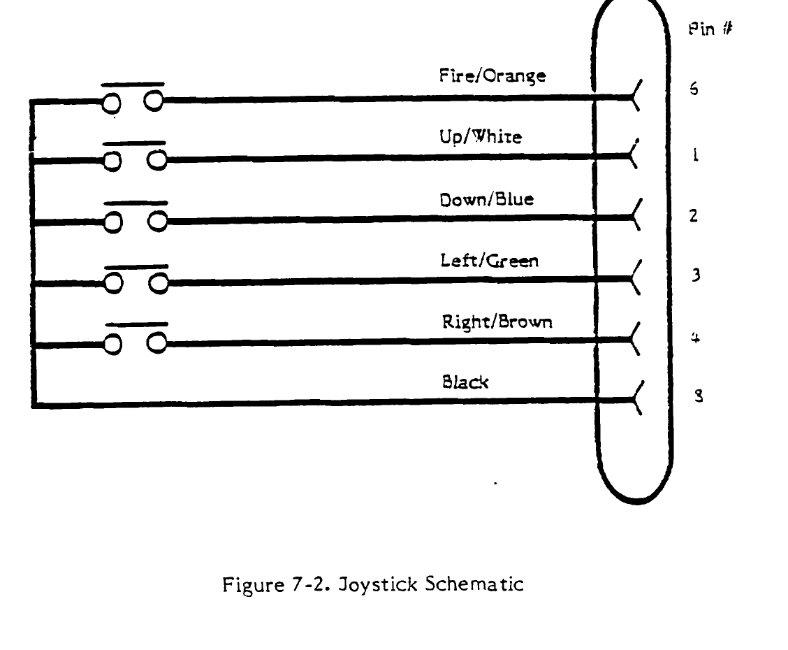
Figure 7-2, "Joystick Schematic", from Atari's 2600/2600A Domestic (M/N) VCS Field Service Manual, p. 7-2: the five switches of the CX40 joystick, the wire colour of each line (fire orange, up white, down blue, left green, right brown, common black) and the plug pin it reaches (6, 1, 2, 3, 4 and 8). Rendered at 200 dpi from PDF page 128 of the hosted manual and cropped to the figure. Used on Atari CX40 Cable Replacement.
Source
[edit | edit source]

File:Atari 2600 and 2600A Field Service Manual.pdf, PDF p. 128.
Author
[edit | edit source]

Atari, Inc.
Licence
[edit | edit source]

Copyright Atari, Inc. Reproduced from the service manual for repair reference, with the source cited. Not freely licensed.
File history
Click on a date/time to view the file as it appeared at that time.
| Date/Time | Thumbnail | Dimensions | User | Comment | |
|---|---|---|---|---|---|
| current | 16:52, 25 October 2026 | | 1,128 × 930 (31 KB) | Josh (talk | contribs) | Upload for CX40 repair guides |
You cannot overwrite this file.
File usage
The following page uses this file:
