

File:Atari STE reset circuit (schematic C300780-001 sheet 1).png

Summary
[edit | edit source]

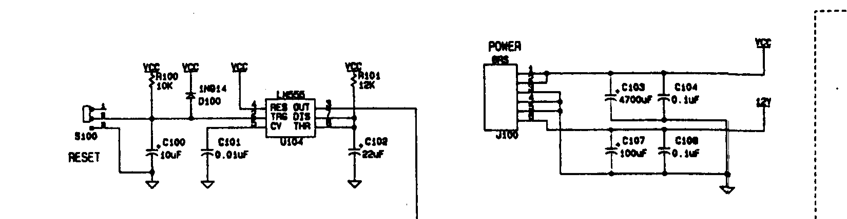
Crop of Atari's STE schematic, drawing C300780-001 revision A (October 1989), sheet 1: the reset circuit and power input. The reset timer U104 is an LM555 whose trigger input is held by C100 (10 µF) and R100 (10 kΩ), with D100 (1N914) to VCC and the reset button S100 to ground; its timing parts are R101 (12 kΩ) and C102 (22 µF), with C101 (0.01 µF) on the control-voltage pin. At the right is the power connector J100 with C103 (4700 µF) and C104 on +5 V and C107 (100 µF) and C108 on +12 V. Cropped from File:Atari STE Schematic Rev A C300780-001.pdf.
Source
[edit | edit source]

File:Atari STE Schematic Rev A C300780-001.pdf (rendered 2026-10-25).
Author
[edit | edit source]

Atari Corporation.
Licence
[edit | edit source]

Copyright Atari Corporation. Hosted for preservation and repair reference, with the source cited.
File history
Click on a date/time to view the file as it appeared at that time.
| Date/Time | Thumbnail | Dimensions | User | Comment | |
|---|---|---|---|---|---|
| current | 11:29, 25 October 2026 | | 1,650 × 428 (19 KB) | Josh (talk | contribs) | Crop of Atari STE schematic for reset repair guide |
You cannot overwrite this file.
File usage
The following page uses this file:
