

File:Casio PV-16 main board.jpg
Summary
[edit | edit source]

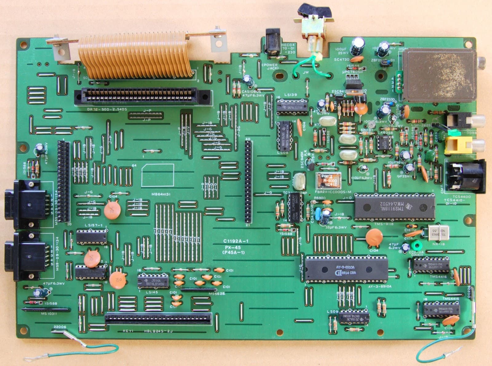
Main board of a Casio PV-16 with the CPU board removed. Visible: the power jack (HEC0470-01-230) and power switch at the top edge, a µPC7805H regulator with electrolytic capacitors marked on the board 100 µF 25 WV and 100 µF 6.3 WV beside it, the RF modulator, video, audio and cassette sockets at the right, the cartridge connector at the top, the joystick connectors at the left and the TMS9118NL video chip and AY-3-8910A sound chip.
Source
[edit | edit source]

MSX Resource Center wiki, file page https://www.msx.org/wiki/File:Pv16b.jpg, current version uploaded by Gdx on 15 February 2016 with the description "MSX1 Personal computer PV-16 [Mainboard]". Retrieved 2026-10-21.

Author
[edit | edit source]

Photograph uploaded to the MSX Resource Center wiki by Gdx; the original photographer is not named there.
Licence
[edit | edit source]

No licence is stated on the source page; copyright remains with the photographer. Hosted for repair reference, with the source cited.
File history
Click on a date/time to view the file as it appeared at that time.
| Date/Time | Thumbnail | Dimensions | User | Comment | |
|---|---|---|---|---|---|
| current | 14:45, 21 October 2026 | | 1,600 × 1,189 (248 KB) | Josh (talk | contribs) | Upload for the Casio PV-7 and PV-16 pages |
You cannot overwrite this file.
File usage
The following 3 pages use this file:
