
File:IBM 5150 16KB-64KB system board memory locations (HMS p. 3-103).png

Summary
[edit | edit source]

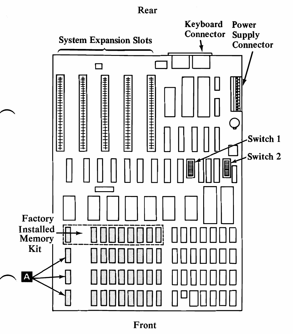
Figure from IBM's Hardware Maintenance and Service manual for the IBM Personal Computer (5150), part 6025072, August 1981, page 3-103 (16 KB Memory Expansion Kit Removal, step 4). Top view of the 16KB-64KB system board with the rear at the top, showing the factory-installed memory kit (bank 0, outlined) and the three socketed banks, with arrow A on the parity position of each, the expansion slots, keyboard connector, power supply connector and switch blocks 1 and 2.
Source
[edit | edit source]

Cropped from page 3-103 (PDF page 278) of File:IBM PC 5150 Hardware Maintenance and Service (August 1981).pdf, rendered at 200 dpi.
Author
[edit | edit source]

IBM Corporation.
Licence
[edit | edit source]

Copyright IBM Corporation. Not freely licensed. Reproduced for repair reference, with the source cited.
File history
Click on a date/time to view the file as it appeared at that time.
| Date/Time | Thumbnail | Dimensions | User | Comment | |
|---|---|---|---|---|---|
| current | 21:31, 25 October 2026 | | 982 × 1,118 (51 KB) | Josh (talk | contribs) | Upload for repair guide |
You cannot overwrite this file.
File usage
The following page uses this file:
