

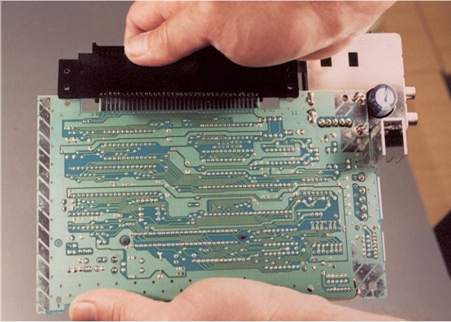
File:NES-001 72-pin connector on PCB (Nintendo ASC manual).jpg
Summary
[edit | edit source]

Photograph of the solder side of an NES-001 PCB with the black 72-pin game pak connector pushed onto the board's edge contacts at the top, and the RF modulator at top right.
Source
[edit | edit source]

Nintendo of America, Authorized Service Center Manual, Field Service Department, revision June 2002, chapter 4, hosted here as File:Nintendo Authorized Service Center Manual June 2002.pdf (described on Nintendo Authorized Service Center Manual (June 2002)), page 28 (PDF page 28). Rendered from the PDF on 25 October 2026.
Author
[edit | edit source]

Nintendo of America Inc.
Licence
[edit | edit source]

Copyright Nintendo of America Inc. Not freely licensed. Hosted for preservation and repair reference, with the source cited.
File history
Click on a date/time to view the file as it appeared at that time.
| Date/Time | Thumbnail | Dimensions | User | Comment | |
|---|---|---|---|---|---|
| current | 09:03, 25 October 2026 | | 649 × 464 (88 KB) | Josh (talk | contribs) | Upload for NES repair guides; source and licence on the description page |
You cannot overwrite this file.
File usage
The following page uses this file:
