

File:Philips NMS 8280 power supply board layout (service manual).png
Size of this preview: 800 × 441 pixels. Other resolution: 2,200 × 1,214 pixels.

Original file (2,200 × 1,214 pixels, file size: 1,003 KB, MIME type: image/png)
Summary
[edit | edit source]

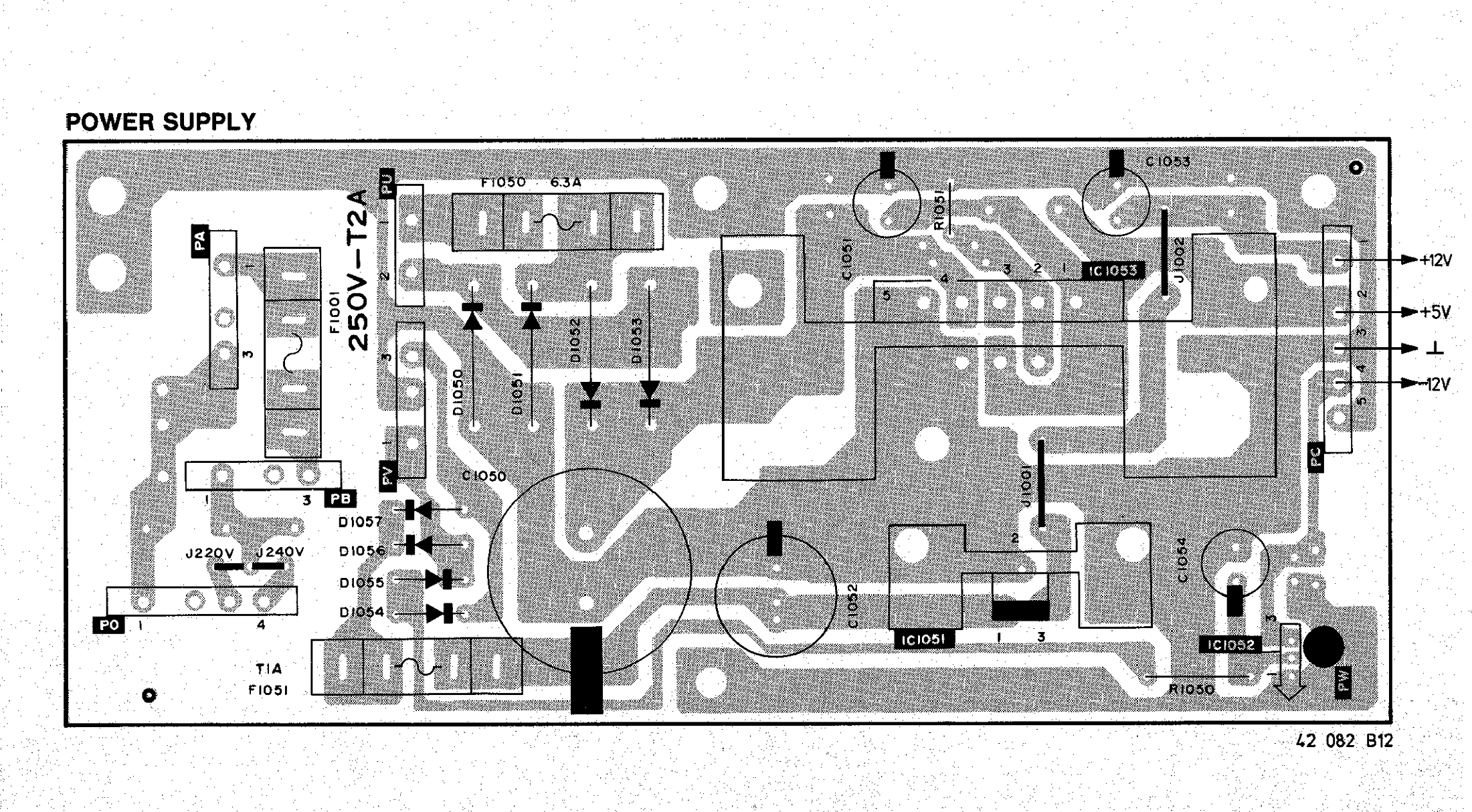
Component layout (drawing 42 082 B12) of the NMS 8280 power supply board: fuses F1001, F1050 and F1051, rectifiers D1050 to D1057, capacitors C1050 to C1054, regulators IC1051 to IC1053, R1050 and R1051, the J220V and J240V mains links, the J1001 and J1002 wire links, and the output connector PC (+12 V, +5 V, ground, -12 V). Cropped from page 42 of the service manual 4822 727 15939.
Source
[edit | edit source]

Rendered from File:Philips NMS 8280 Service Manual 4822 727 15939.pdf, page 42.
Author
[edit | edit source]

Philips Service Consumer Electronics.
Licence
[edit | edit source]

Copyright Philips. Hosted for preservation and repair reference, with the source cited.
File history
Click on a date/time to view the file as it appeared at that time.
| Date/Time | Thumbnail | Dimensions | User | Comment | |
|---|---|---|---|---|---|
| current | 14:44, 21 October 2026 | | 2,200 × 1,214 (1,003 KB) | Josh (talk | contribs) | NMS 8280 power supply board layout from the service manual |
You cannot overwrite this file.
File usage
The following page uses this file:
