

File:Philips VG-8000 and VG-8010 exploded view (service manual).png

Summary
[edit | edit source]

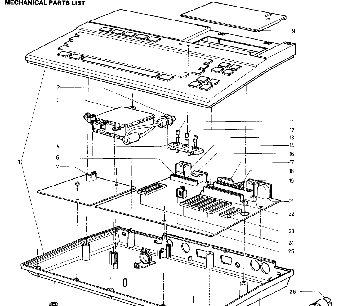
Exploded view of the Philips VG 8000 and VG 8010 from the mechanical parts list of the service manual: cabinet with keyboard (1), UHF modulator and cable (2, 3), LED holder and LEDs (4, 11 to 13), keyboard socket (6), the PAL or RGB encoder board at the left, the main board with the audio/video, joystick, cassette and power connectors, reset button, cartridge sockets and IC sockets, and the cartridge slot cover (9). Rendered from PDF page 15 of the service manual.
Source
[edit | edit source]

Rendered from File:Philips VG-8000 VG-8010 Service Manual.pdf, page 15.
Author
[edit | edit source]

Philips Service Consumer Electronics.
Licence
[edit | edit source]

Copyright Philips. Hosted for preservation and repair reference, with the source cited.
File history
Click on a date/time to view the file as it appeared at that time.
| Date/Time | Thumbnail | Dimensions | User | Comment | |
|---|---|---|---|---|---|
| current | 12:56, 21 October 2026 | | 1,119 × 988 (66 KB) | Josh (talk | contribs) | VG 8000 / VG 8010 exploded view from the service manual |
You cannot overwrite this file.
File usage
The following 4 pages use this file:
