

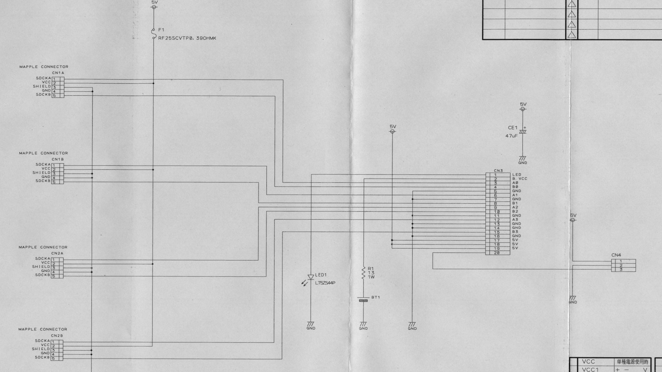
File:Sega Dreamcast sub board 2 schematic 839-1124.png

Summary
[edit | edit source]

Schematic of the Dreamcast controller-port board, KATANA SUB BD 2, part 839-1124, cropped from Sega's EU service manual page 8-25. It shows the 5 V feed from CN3 pins 17 to 19 through F1 (RF25SCVTP 0.39 Ω) to pin 2 (VCC) of the four Maple connectors CN1A, CN1B, CN2A and CN2B; the clock cell BT1 fed from CN3 pin 2 (B.VCC) through R1 (13 Ω 1 W); LED1; CE1 (47 µF) on 5 V; and the fan connector CN4.
Source
[edit | edit source]

Sega Enterprises, Ltd., Service Manual: Dreamcast EU, No. 022-EU, October 1999, p. 8-25, hosted on this wiki as File:Sega Dreamcast EU Service Manual 022-EU.pdf (PDF page 35)
Author
[edit | edit source]

Sega Enterprises, Ltd.
Licence
[edit | edit source]

Copyright Sega Enterprises, Ltd. Hosted for preservation and repair reference, with the source cited.
File history
Click on a date/time to view the file as it appeared at that time.
| Date/Time | Thumbnail | Dimensions | User | Comment | |
|---|---|---|---|---|---|
| current | 10:29, 25 October 2026 | | 2,200 × 1,237 (914 KB) | Josh (talk | contribs) | Upload for Dreamcast repair guides |
You cannot overwrite this file.
File usage
The following page uses this file:
