

File:Sega Master System (Model 1) controller port schematic.png

Summary
[edit | edit source]

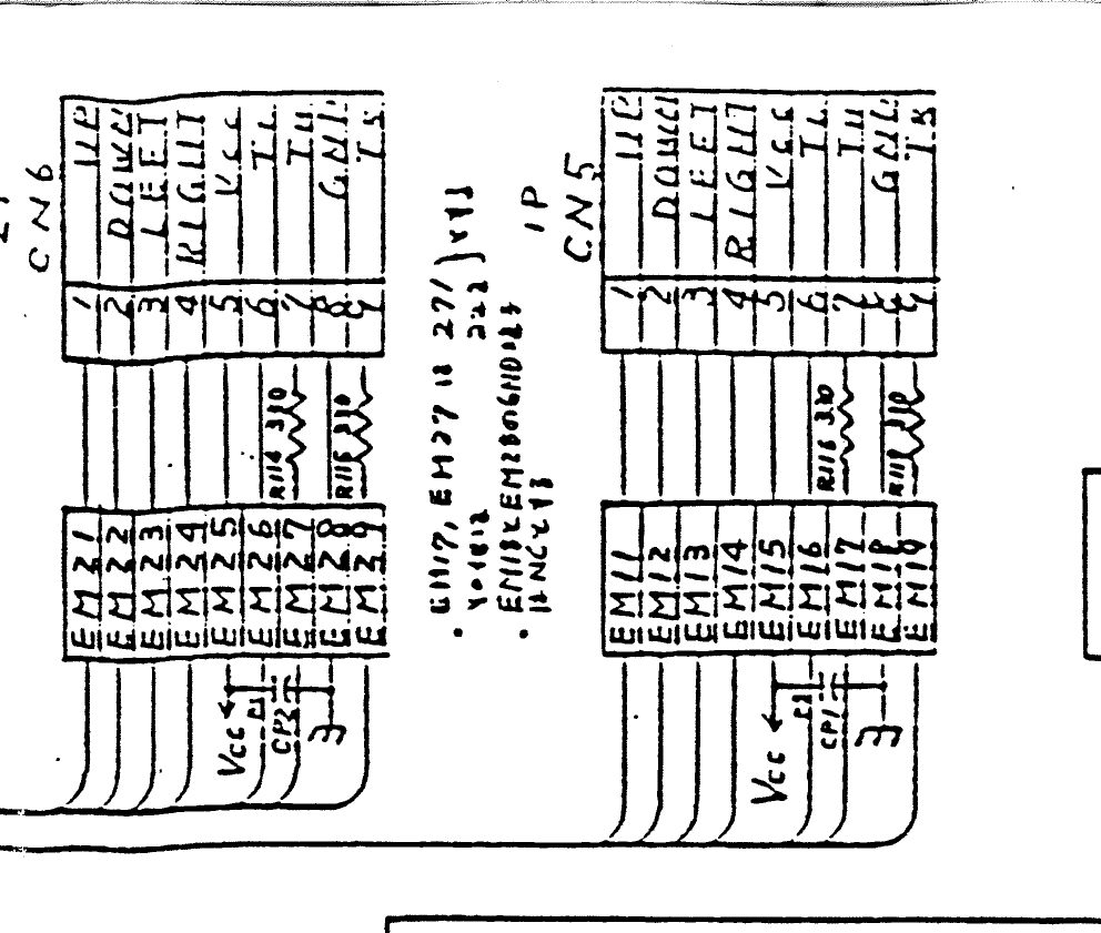
Crop of Sega's schematic "IC Board PB PAL VA1" (171-5534), sheet 1, showing the two controller ports CN6 (2P) and CN5 (1P), pins 1 UP, 2 DOWN, 3 LEFT, 4 RIGHT, 5 Vcc, 6 TL, 7 TH, 8 GND and 9 TR, each line passing through an EMI filter (EM21 to EM29 and EM11 to EM19), with the 330 Ω resistors R114 to R117 and the decoupling capacitors CP1 and CP2.
Source
[edit | edit source]

Sega Enterprises, Ltd., Sega Master System Service Manual (Power Base, PAL), schematic p. 13 (PDF p. 14), hosted on this wiki as File:Sega Master System (Model 1) Service Manual.pdf
Author
[edit | edit source]

Sega Enterprises, Ltd.
Licence
[edit | edit source]

Copyright Sega Enterprises, Ltd. Hosted for preservation and repair reference, with the source cited.
File history
Click on a date/time to view the file as it appeared at that time.
| Date/Time | Thumbnail | Dimensions | User | Comment | |
|---|---|---|---|---|---|
| current | 10:57, 25 October 2026 | | 992 × 841 (49 KB) | Josh (talk | contribs) | Upload for Master System repair guides |
You cannot overwrite this file.
File usage
The following page uses this file:
