

File:Sinclair QL IC22 area component layout (Issue 5).png

Summary
[edit | edit source]

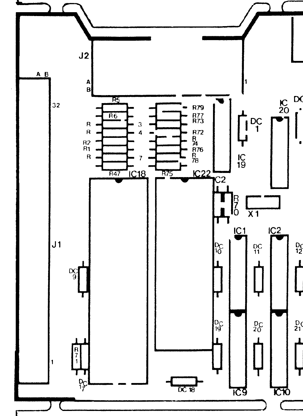
Part of the Issue 5 main board component layout at the expansion-connector end: the expansion connector J1, the 68008 (IC18), the ZX8301 (IC22) with its pin 1 notch, the 15 MHz crystal X1 and the ROM cartridge slot J2. Cropped from Figure 5.1 of Sinclair's QL Service Manual (issue 3, October 1985), page 5.11 (PDF page 73) of the hosted copy File:Sinclair QL Service Manual.pdf. Used on Sinclair QL RGB Port Repair.
Source
[edit | edit source]

Cropped for this wiki from File:Sinclair QL PCB component layout (Issue 5).png, the wiki's copy of Figure 5.1; no other change.

Author
[edit | edit source]

Sinclair Research Ltd
Licence
[edit | edit source]

Copyright Sinclair Research Ltd. Not freely licensed. Hosted for preservation and repair reference, with the source cited.
File history
Click on a date/time to view the file as it appeared at that time.
| Date/Time | Thumbnail | Dimensions | User | Comment | |
|---|---|---|---|---|---|
| current | 10:42, 25 October 2026 | | 1,020 × 1,400 (32 KB) | Josh (talk | contribs) | Crop for Sinclair QL RGB Port Repair |
You cannot overwrite this file.
File usage
The following page uses this file:
