

File:Sinclair ZX Spectrum Issue 3 regulator and power input circuit.png
Summary
[edit | edit source]

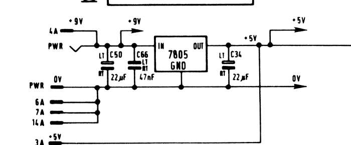
Crop of Sinclair's ZX Spectrum Issue 3 circuit diagram showing the power input: the PWR socket, the +9 V edge-connector contact 4A, C50 (22 µF) and C66 (47 nF) on the regulator input, the 7805, C34 (22 µF) on the output, the 0 V contacts 6A, 7A and 14A and the +5 V contact 3A. Cropped at full resolution for Sinclair ZX Spectrum Voltage Regulator Replacement.
Source
[edit | edit source]

Cropped from File:Sinclair ZX Spectrum Issue 3 circuit diagram.png, itself a copy of "ZX Spectrum Issue 3 - Schaltbild.gif" in the Sinclair ZX Computers Archive.

Author
[edit | edit source]

Sinclair Research Ltd
Licence
[edit | edit source]

Copyright Sinclair Research Ltd. Not freely licensed. Hosted for preservation and repair reference.
File history
Click on a date/time to view the file as it appeared at that time.
| Date/Time | Thumbnail | Dimensions | User | Comment | |
|---|---|---|---|---|---|
| current | 11:08, 25 October 2026 | | 700 × 290 (14 KB) | Josh (talk | contribs) | Image for the Spectrum regulator guide |
You cannot overwrite this file.
File usage
The following page uses this file:
