

File:Super Famicom power switch harness polarity (Nintendo service manual).png

Summary
[edit | edit source]

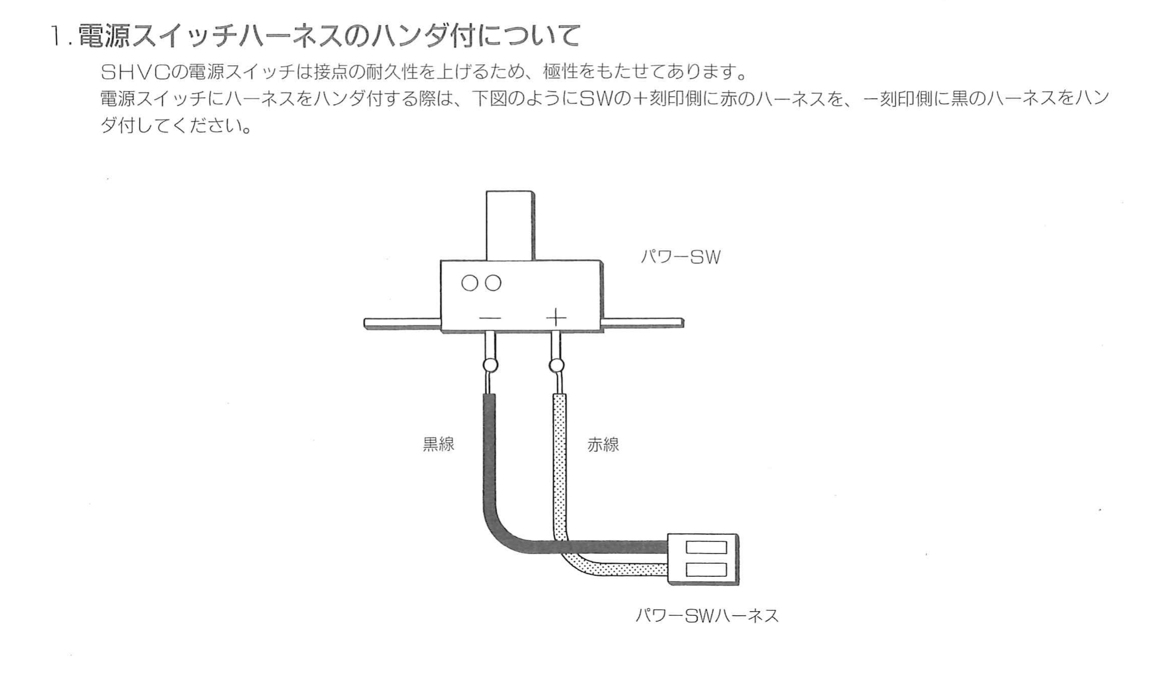
Nintendo's instruction for soldering the Super Famicom power-switch harness. The text says the SHVC power switch is polarised to extend the life of its contacts, and that the red harness wire (赤線) goes to the side of the switch marked + and the black wire (黒線) to the side marked −. The drawing shows the switch, its two terminals and the two-pin harness connector.
Source
[edit | edit source]

Cropped from Nintendo's ファミコン・スーパーファミコン・ゲームボーイ サービスマニュアル (Famicom / Super Famicom / Game Boy Service Manual), 1992, printed page 11 (PDF page 7), hosted here as File:Nintendo Famicom Service Manual.pdf; described on Nintendo Famicom Service Manual. Rendered at 300 dpi and converted to greyscale.
Author
[edit | edit source]

Nintendo Co., Ltd.
Licence
[edit | edit source]

Copyright Nintendo Co., Ltd. Hosted for preservation and repair reference, with the source cited. Not freely licensed.
File history
Click on a date/time to view the file as it appeared at that time.
| Date/Time | Thumbnail | Dimensions | User | Comment | |
|---|---|---|---|---|---|
| current | 10:46, 25 October 2026 | | 2,282 × 1,345 (180 KB) | Josh (talk | contribs) | Upload for SNES repair guide |
You cannot overwrite this file.
File usage
The following page uses this file:
