

File:Tandon TM100 servo circuit board schematic (manual B-8).png

Summary
[edit | edit source]

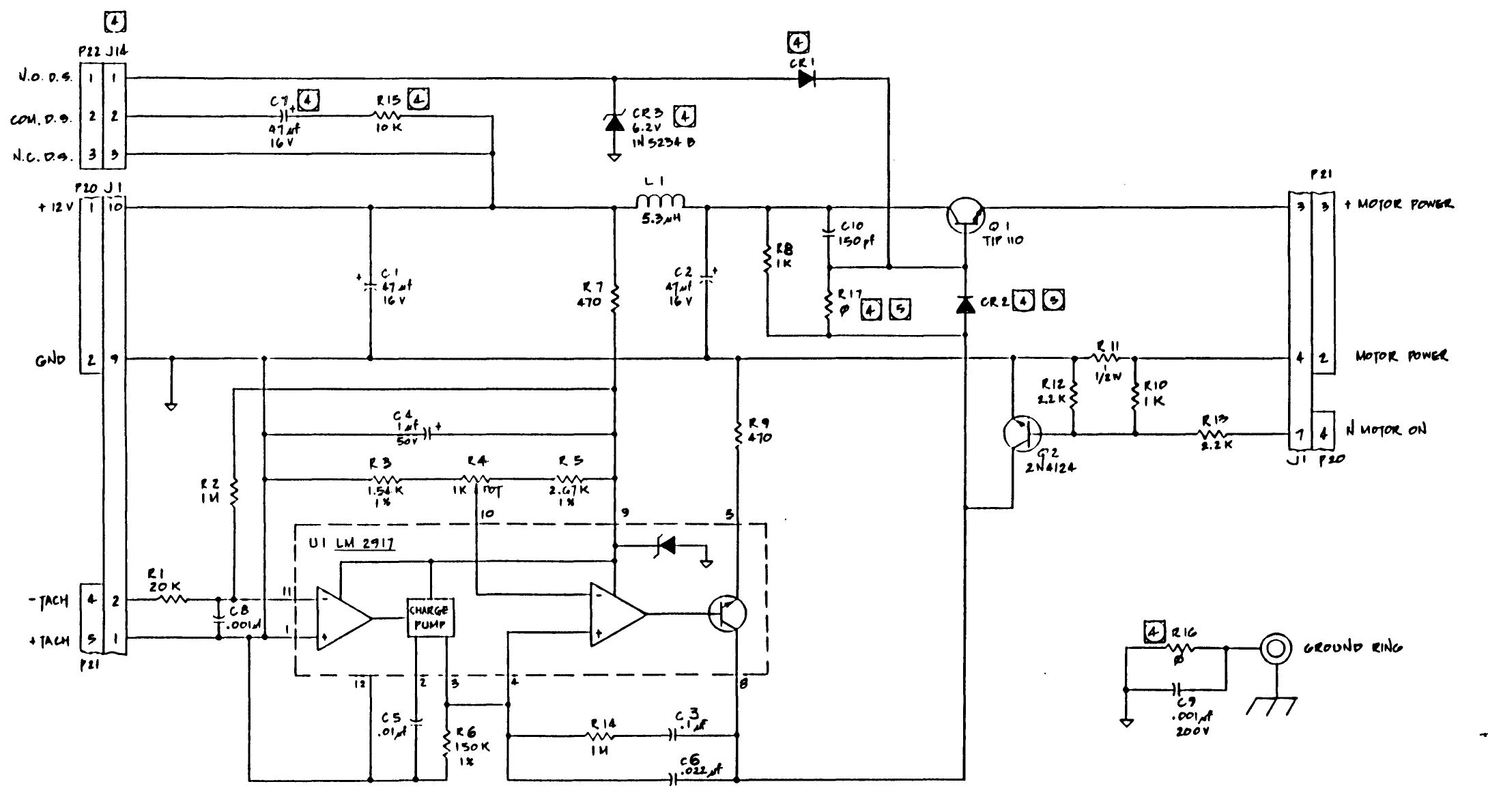
Tandon's servo circuit board schematic for the TM100-1 / TM100-2 floppy drives, drawing 180001 Rev F, sheet 1 of 1. It shows the LM2917 frequency-to-voltage converter U1, the speed potentiometer R4 (1 kΩ) between R3 and R5, the motor drive transistor Q1 (TIP110), the motor on/off transistor Q2 (2N4124), the tachometer input on P21 and the connectors J1 and J14. Rendered at 200 dpi from page B-8 of the manual and cropped; the title block, notes and the board-version table were left out of the crop, and a stray fragment of that table at the lower right was blanked.
Source
[edit | edit source]

Tandon Corporation, OEM Operating and Service Manual, TM100-1, TM100-2 Disk Drives, 48 Tracks Per Inch, 179022-001 Rev. B (1983), Appendix B, p. B-8 (PDF page 102), hosted here as File:Tandon TM100-1 TM100-2 48TPI Operating and Service Manuals 1983.pdf.
Author
[edit | edit source]

Tandon Corporation
Licence
[edit | edit source]

Copyright Tandon Corporation, 1983. Not freely licensed. Reproduced for repair reference, with the source cited.
File history
Click on a date/time to view the file as it appeared at that time.
| Date/Time | Thumbnail | Dimensions | User | Comment | |
|---|---|---|---|---|---|
| current | 19:41, 25 October 2026 | | 2,180 × 1,190 (60 KB) | Josh (talk | contribs) | Upload for repair guide |
You cannot overwrite this file.
File usage
The following page uses this file:
