
Tandon TM100-2 Spindle Speed Adjustment

The Tandon TM100-2 turns its spindle with a belt from a DC motor that has a built-in tachometer, and a servo circuit board at the rear of the chassis holds the speed at 300 RPM.[1] Tandon's tolerance is 300 RPM ± 1.5 %, which is 295.5 to 304.5 RPM.[2][3] The speed is set with one potentiometer, R4, on the servo board, and checked against strobe rings printed on the spindle pulley.[4] Tandon's manual gives the same check and adjustment for the single-sided Tandon TM100-1, and both drives use the same servo board part number.[4][5]
Tandon calls this the long-term speed adjustment. It is needed after the belt, the servo board or the drive motor has been replaced, and when a drive reads its own disks badly or not at all.[4][6]
Symptoms
[edit | edit source]- Read errors, or disks written in this drive that other drives cannot read. A drive running outside 295.5 to 304.5 RPM is out of Tandon's specification.[2][3]
- The spindle does not turn at all, or turns slowly. Tandon's troubleshooting table lists, in order: no Motor On signal from the interface, loose or missing connectors P13, P20 and P21, a loose or missing drive belt, a faulty servo board, a faulty logic board and a faulty drive motor.[7] Tandon's belt replacement steps are on the main page, under Drive belt.
Disks that read in this drive but not in others, and the reverse, can also be a head alignment fault. Check the speed first, because Tandon's own index and alignment checks start from a drive running at the right speed.[8][3] For other drive faults see the 5150 troubleshooting guide and Floppy Drive Repair.
How the speed control works
[edit | edit source]
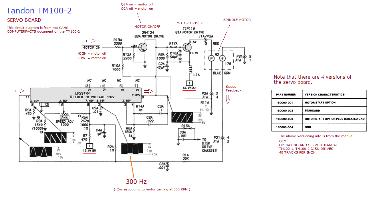
The motor's tachometer winding feeds a 12 V AC signal back to the servo board on pins 1 and 2 of its connector J1.[9] On Tandon's schematic it goes to U1, an LM2917 frequency-to-voltage converter. R4, a 1 kΩ potentiometer between R3 (1.54 kΩ, 1 %) and R5 (2.67 kΩ, 1 %), sets the DC reference on U1 pin 10, and U1 drives the motor current through Q1, a TIP110. Q2, a 2N4124, switches the motor on and off from the N MOTOR ON line on J1 pin 7.[10][9] Minuszerodegrees measures the tachometer frequency on U1 pin 2 and gives 300 Hz as the reading for a spindle turning at 300 RPM.[3][11]
Tandon lists four versions of the servo board (180000-001 to -004). They differ in a motor start option and in ground isolation, not in the speed control: R3, R4 and R5 are common to all four.[10]
Tools and parts
[edit | edit source]- A small flat-blade screwdriver for R4.[12][3]
- A way of measuring the speed: strong mains-powered fluorescent light for the strobe rings, ImageDisk's Test RPM command on a PC that can run it, or a digital oscilloscope or frequency meter on U1 pin 2.[4][3]
- A host computer or drive exerciser to turn the motor on, and a scratch diskette. Tandon's check uses a work diskette in the drive; minuszerodegrees turns the motor on from Cassette BASIC or DEBUG without a diskette.[4][13]
- A meter for the supply rails.[4]
- Replacement parts, if needed: drive belt 914000-001, servo circuit board 171147-002 (standard) and drive motor 171014-001.[5]
Procedure
[edit | edit source]Preparation
[edit | edit source]- Leave the drive connected to its controller and power supply. In an IBM PC or XT, remove the system unit cover so the underside of the drive can be seen, or take the drive out and run it on the bench from the same cable.
- Check the supply at the drive: +12 V within ± 0.6 V and +5 V within ± 0.25 V. The drive's power connector J2 has +12 V on pin 1, +12 V return on pin 2, +5 V return on pin 3 and +5 V on pin 4.[4][14]
- Turn the spindle pulley by hand with the power off. It should turn freely.[15] Check that the belt is on both pulleys and that the screw in the centre of the spindle pulley is tight; minuszerodegrees cured one speed fault by tightening that screw.[3]
Running the motor
[edit | edit source]The IBM BIOS switches the drive motor off a few seconds after it was last used, so for a long measurement the motor has to be switched on continuously.[13]
- From Cassette BASIC on an IBM 5150 or 5160, type
OUT 1010,20to turn on the LED and motor of drive A:, orOUT 1010,37for drive B:. This runs the motor for a few seconds only.[13] - To keep drive A: turning, enter and run this two-line program, and stop it with Ctrl-Break when finished; the drive runs on for a few seconds after.[16]
10 OUT 1010,20
20 GOTO 10 RUN
- From DOS, DEBUG's command
o 3f2 14does the same for drive A: ando 3f2 25for drive B:.[17] - Tandon's own check is made with a work diskette inserted and the latch closed, so the spindle is under its normal load. Insert a scratch diskette before measuring.[4]
Checking the speed
[edit | edit source]

Use one of these methods.
- Strobe rings: turn the drive over so that the timing disk on the spindle pulley is visible. The outer ring of bars is for 60 Hz mains lighting and the inner ring for 50 Hz. Under fluorescent light powered from the mains, with the motor running, the ring for your mains frequency should stand still.[4] Tandon's text names only the 60 Hz ring. In the UK and the rest of the 50 Hz world use the inner ring, as Tandon's Figure 5-4 and minuszerodegrees both show. The light must be strong; minuszerodegrees found LED ceiling lights did a reasonable but not great job, and expects a little movement even on a good drive.[3]
- ImageDisk: run its Test RPM command, which reports the speed directly.[3]
- Oscilloscope or frequency meter: measure at pin 2 of U1, the LM2917 on the servo board. 300 Hz corresponds to 300 RPM, so the limits are 295.5 to 304.5 Hz.[3][11]
Adjusting R4
[edit | edit source]- Find R4 on the servo board at the rear of the drive. On Tandon's drawing it is the upright potentiometer on the left half of the board, marked "spindle speed control"; J1, the connector that carries the motor and tachometer wiring, is at the right-hand end.[4]
- With the motor running, turn R4 slowly with the screwdriver until the strobe ring stands still, or until the measured speed is 300 RPM (300 Hz at U1 pin 2).[4][3]
- Stop the motor and start it again, then repeat the check. The setting should hold from a cold start.
If the speed will not adjust
[edit | edit source]Tandon's troubleshooting table sends a drive that fails the speed check to the same list as a spindle that will not turn: the Motor On signal, connectors P13, P20 and P21, the drive belt, the servo board, the logic board and the drive motor, in that order.[7] Minuszerodegrees adds a loose screw on the spindle flywheel, and suggests that the spindle itself may need lubricating.[3]
On the servo board, the electrolytic capacitors are C1 and C2 (47 µF 16 V, on the +12 V supply either side of L1), C4 (1 µF 50 V) and, on the motor start versions 180000-001 and -003 only, C7 (47 µF 16 V).[10] See Capacitor Failure Symptoms and Testing Diodes, Transistors and Regulators for checking them and Q1.
After replacing the belt, servo board or drive motor, Tandon's table of checks calls for the drive motor speed check again.[6]
Testing
[edit | edit source]- The strobe ring for your mains frequency stands still, or the measured speed is between 295.5 and 304.5 RPM.[2]
- Format a scratch diskette in the drive and read it back, then read a disk written on a known-good 360 KB drive. If the drive reads its own disks but not others after the speed is correct, see Tandon TM100-2 Head Alignment; minuszerodegrees advises against attempting an alignment unless that is clearly the fault.[3]
Related pages
[edit | edit source]- Tandon TM100-2
- Tandon TM100-1
- Tandon TM100-2: drive belt
- Tandon TM100-2 Head Alignment
- Tandon TM100-2 Track 0 Switch Repair
- IBM PC (5150) Maintenance Guide#Floppy drives
- IBM PC XT Maintenance Guide
- Floppy Drive Repair
- Switch and Potentiometer Repair
References
[edit | edit source]- ↑ Tandon Corporation, OEM Operating and Service Manual, TM100-1, TM100-2 Disk Drives, 48 Tracks Per Inch, 179022-001 Rev. B (1983), section 1.5 p. 1-2 and section 4 p. 4-10: belt-driven spindle, DC motor with integral tachometer, servo board at the rear of the chassis, 300 RPM. Hosted as File:Tandon TM100-1 TM100-2 48TPI Operating and Service Manuals 1983.pdf.
- ↑ 2.0 2.1 2.2 Tandon, TM100 manual (1983), Table 2-1, p. 2-3: disk rotational speed 300 RPM ± 1.5 percent; motor start time 250 ms maximum.
- ↑ 3.00 3.01 3.02 3.03 3.04 3.05 3.06 3.07 3.08 3.09 3.10 3.11 3.12 Minuszerodegrees.net, "Tandon TM100-2 in IBM 5150/5155/5160 – Known Problems/Issues", section "Incorrect spindle speed": the 295.5 to 304.5 RPM limits, R4 on the servo board, the loose flywheel screw, spindle lubrication, and the three measuring methods (LM2917 pin 2, ImageDisk Test RPM, strobe rings under strong mains-powered light).
- ↑ 4.00 4.01 4.02 4.03 4.04 4.05 4.06 4.07 4.08 4.09 4.10 Tandon, TM100 manual (1983), section 5.5 "Drive Motor Speed Check and Adjustment", pp. 5-3 to 5-5, with Figure 5-3 (location of R4) and Figure 5-4 (bottom view of the drive, timing disk rings for 60 Hz and 50 Hz).
- ↑ 5.0 5.1 Tandon, TM100 manual (1983), Appendix A "Recommended Spares and Major Assemblies", p. A-1: drive belt 914000-001, servo circuit board 171147-002, drive motor 171014-001.
- ↑ 6.0 6.1 Tandon, TM100 manual (1983), Table 6-2 "Guide to Checks and Adjustments", p. 6-6: checks required after replacing the drive belt, servo board or drive motor assembly.
- ↑ 7.0 7.1 Tandon, TM100 manual (1983), Table 6-1 "Troubleshooting Guide", pp. 6-2 and 6-4: "Spindle speed out of tolerance or not turning" and "Fails drive motor speed check and adjustment".
- ↑ Tandon, TM100 manual (1983), section 5.7 "Index Checks and Adjustment", step 4 "Check the speed of the drive's motor", p. 5-9.
- ↑ 9.0 9.1 Tandon, TM100 manual (1983), "Spindle Motor Control Circuit", p. 4-12, and Figure 4-10: Spindle Motor Enable on pin 7, potentiometer reference, tachometer feedback on pins 1 and 2, 12 V AC tachometer signal.
- ↑ 10.0 10.1 10.2 Tandon, TM100 manual (1983), Appendix B, Servo Circuit Board Schematic, drawing 180001 Rev F, sheet 1 of 1, p. B-8 (PDF page 102), with its Table I of board versions.
- ↑ 11.0 11.1 Minuszerodegrees.net, "Tandon TM100-2 servo board", an annotated copy of the servo board circuit from Sams COMPUTERFACTS, marking 300 Hz at U1 pin 2 for 300 RPM.
- ↑ Tandon, TM100 manual (1983), section 5.2 "Equipment Required", pp. 5-1 and 5-2.
- ↑ 13.0 13.1 13.2 Minuszerodegrees.net, "Floppy – Some BASIC statements and programs", "Turn on drive's LED and spindle motor": OUT 1010,20 for A: and OUT 1010,37 for B:, no diskette needed, and the BIOS motor timeout.
- ↑ Tandon, TM100 manual (1983), section 3.5 "D. C. Power", Table 3-2, p. 3-5: J2 pin assignments.
- ↑ Tandon, TM100 manual (1983), section 5.1 "Visual Inspection", p. 5-1: rotate the drive hub by hand; it should rotate freely.
- ↑ Minuszerodegrees.net, continuous motor-on program for drive A:.
- ↑ Minuszerodegrees.net, "Floppy – Some DEBUG commands and programs": o 3f2 14 for drive A: and o 3f2 25 for drive B:.