

Macintosh Classic II Capacitor Replacement Guide
The Macintosh Classic II logic board uses surface-mount electrolytic capacitors, and the board carries a 1/2 AA lithium cell. Recap-a-Mac describes the Classic II as very prone to both capacitor and battery leakage, and advises that a machine whose battery and capacitors have not been changed should be seen to straight away.[1] The Classic and Classic II share a power/sweep board but not a logic board.
Safety
[edit | edit source] | The CRT anode holds charge after power-off. Discharge it before working on the power/sweep board, the anode lead or the CRT socket board: see CRT Discharge Procedure. Apple's Service Guide says the Classic II's CRT is discharged to the ground lug to avoid damaging the logic board.[2]
The power/sweep board is a mains-connected switch-mode supply. CP1 (and CP13 where it is a capacitor) is the primary reservoir; on a 110 V board the pair is charged to about 306 V DC, and it holds charge after the machine is unplugged.[3] Measure across it before touching the primary side. Apple's warning on the battery: "If handled or discarded improperly, the lithium battery in the computer could explode."[4] |
Battery first
[edit | edit source]Apple's verification procedure is to remove the logic board, set the meter to the 10 V DC range, measure across the cell, and replace it if it reads below 3.0 V.[4] The Apple part number for the cell is 742-0011.[5] Take the cell out before doing anything else. Recap-a-Mac reports that the brand of 1/2 AA cell used in the Classic sprays electrolyte over the logic board, in some cases beyond repair.[6] The cell is lithium, so neutralise its residue with bicarbonate of soda, not vinegar. See Battery Explosion, Capacitor or Corrosion Damage.
Capacitor inspection
[edit | edit source]Recap-a-Mac reports leakage on this board.[1] Look for dark haloes or dried crust at the base of the cans, dull or green solder on nearby IC pins, and thinned or broken traces, best seen under a loupe with light raking across the board. See Capacitor Failure Symptoms.
Logic board
[edit | edit source]Two versions exist. The earlier has four ROM chips at the bottom right and 13 surface-mount electrolytics; the later has two ROM chips and 17.[1] In Recap-a-Mac's photographs the 13-capacitor board carries bar-code label 630-0401-B and silkscreen 820-0401-B, and the 17-capacitor board carries label 630-0055-B.[1][7]
| Reference | Capacitance | Voltage | Fitted on |
|---|---|---|---|
| C3 | 47 µF | 16 V | Both |
| C4 | 47 µF | 16 V | Both |
| C5 | 10 µF | 16 V | Both |
| C6 | 10 µF | 16 V | Both |
| C7 | 10 µF | 16 V | Both |
| C8 | 10 µF | 16 V | Both |
| C9 | 1 µF | 50 V | Both |
| C10 | 10 µF | 16 V | Both |
| C11 | 10 µF | 16 V | Both |
| C12 | 10 µF | 16 V | Both |
| C13 | 47 µF | 16 V | Both |
| C14 | 10 µF | 16 V | Both |
| C15 | 1 µF | 50 V | Both |
| C21 | 10 µF | 16 V | 630-0055 only |
| C74 | 10 µF | 16 V | 630-0055 only |
| C79 | 10 µF | 16 V | 630-0055 only |
| C106 | 10 µF | 16 V | 630-0055 only |
The designators and board numbers are Console5's.[8] Recap-a-Mac's photographic guides count 8 × 10 µF 16 V, 3 × 47 µF 16 V and 2 × 1 µF 50 V on the 13-capacitor board, and 12 × 10 µF, 3 × 47 µF and 2 × 1 µF on the 17-capacitor board, which matches Console5's totals.[1][7] BOMARC's schematic of board 820-0401-B gives all 13 positions marked "Both" with the same values: C5, C13 and C14 on sheet 1 and the other ten in the audio circuit on sheet 6.[9] The drawing also has smaller polarised parts that neither kit list includes: four 4.7 µF 16 V on the +5 V rail, C74 4.7 µF 16 V, and 3.3 µF 16 V at C36, C48, C71, C76, C84 and C93.[9] In Recap-a-Mac's photograph of the 630-0055 board, C71 is a moulded rectangular chip marked "3.3 16V", not an aluminium can, and C74 is one of the four extra 10 µF 16 V electrolytics.[7] Count the parts on your own board before ordering.
-
 Classic II 13-capacitor logic board, 630-0401-B (Recap-a-Mac)
-
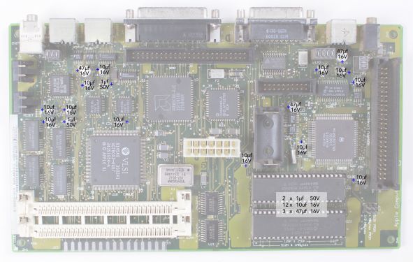 Classic II 17-capacitor logic board, 630-0055-B (Recap-a-Mac)


Power/sweep board
[edit | edit source]The Classic and Classic II share this board.[10] Apple lists four field-replaceable versions: 661-0597 (110 V, Rev. A), 661-0599 (220 V, Rev. A), 661-0651 (110 V, Rev. B) and 661-0652 (220 V, Rev. B).[5] Rev. A and Rev. B boards are not interchangeable: each must be used with the matching CRT yoke assembly.[11]
Identify the mains version first
[edit | edit source] | The primary reservoir is either CP1 and CP13 in series, two 220 µF 250 V capacitors that each carry about half of the voltage, or, on some 220–240 V boards, a single 220 µF 400 V capacitor with no second capacitor fitted. 240 V mains rectifies to about 340 V DC. A single reservoir capacitor takes all of it, so a 250 V part there is over its rating. |
The bare boards carry 630- numbers. What the sources show for the mains input of each:
| Board | Source | CP1 | CP13 | Notes |
|---|---|---|---|---|
| 630-0395 | Console5; BOMARC 820-0395-A ("early") | 220 µF 250 V | 220 µF 250 V | Voltage doubler; JP1 is a wire link marked "cut for 220 VAC input"; +306 V across the pair |
| 630-0420 | Console5 (240 V version of the 630-0395 list) | 220 µF 400 V | 220 µF 400 V | |
| 630-0525 | Console5; BOMARC 820-0525-A ("late") | 220 µF 250 V | 220 µF 250 V | JP1 marked "cut for 240 VAC input"; +306 V across the pair |
| 630-0525 (240 V board) | Recap-a-Mac photograph | One 220 µF 400 V capacitor; no second reservoir capacitor | Bar-code label 630-0525; fuse marked "FP1 T3.15A/250V" | |
| 630-0560 (120 V list) | Console5 | 220 µF 250 V | 220 µF 250 V | |
| 630-0560 (240 V list) | Console5 | 220 µF 400 V | jumper, no capacitor | |
Sources: Console5's board pages,[12][13][14] and BOMARC's schematics for 630-0395 and 630-0525.[3] Recap-a-Mac's photograph of a 240 V board, bar-code label 630-0525, shows one 220 µF 400 V reservoir capacitor and no 250 V electrolytic.[10]
To identify a board, read the 661- label, then look at what is fitted: the 630- number alone does not settle it, because 630-0525 appears with both arrangements. Read the reservoir capacitor's printed rating and check whether CP13 is a capacitor or a wire link. If only one reservoir capacitor is fitted, it must be a 400 V part.
Later layout (630-0525 and the 630-0560 240 V list)
[edit | edit source]| Reference | Capacitance | Voltage |
|---|---|---|
| CF1 | 47 µF | 25 V |
| CF2 | 220 µF | 16 V |
| CF3 | 1000 µF | 16 V |
| CF4 | 470 µF | 25 V |
| CL1 | 1000 µF | 25 V |
| CL2 | 4.7 µF | 250 V |
| CL3 | 1 µF | 50 V |
| CL11 | 47 µF | 16 V |
| CP1 | 220 µF | 250 V where CP13 is also a capacitor; 400 V where it is the only reservoir capacitor (Console5's 630-0560 240 V list; Recap-a-Mac's 240 V 630-0525) |
| CP2 | 470 µF | 50 V |
| CP3 | 10 µF | 25 V |
| CP4 | 47 µF | 25 V |
| CP5 | 1 µF | 50 V |
| CP6 | 2200 µF | 10 V |
| CP7 | 1000 µF | 10 V |
| CP8 | 2200 µF | 16 V |
| CP9 | 470 µF | 25 V |
| CP10 | 470 µF | 25 V |
| CP11 | 220 µF | 50 V |
| CP12 | 1000 µF | 16 V |
| CP13 | 220 µF 250 V on boards with a 250 V CP1; a jumper, no capacitor, on Console5's 630-0560 240 V list | |
| CP34 | 1 µF | 50 V |
| CP36 | 2200 µF | 10 V |
| CP37 | 1 µF | 50 V |
| CV2 | 470 µF | 10 V |
From Console5's lists for 630-0525 and the 630-0560 240 V version, which differ only at CP1 and CP13.[13][14] Recap-a-Mac's photograph of a 240 V 630-0525 board marks the same values and quantities, including four 1 µF 50 V parts (Console5's CL3, CP5, CP34 and CP37); the summary box printed on the photograph says two.[10]

Earlier layout (630-0395)
[edit | edit source]| Reference | Capacitance | Voltage |
|---|---|---|
| CF1 | 47 µF | 25 V |
| CF2 | 220 µF | 16 V |
| CF3 | 1000 µF | 16 V |
| CF4 | 470 µF | 25 V |
| CL1 | 10 µF | 50 V |
| CL2 | 4.7 µF | 250 V |
| CL3 | 1 µF | 50 V |
| CP1 | 220 µF | 250 V |
| CP2 | 1000 µF | 35 V |
| CP3 | 10 µF | 25 V |
| CP4 | 47 µF | 25 V |
| CP5 | 1 µF | 50 V |
| CP6 | 2200 µF | 10 V |
| CP7 | 1000 µF | 10 V |
| CP8 | 2200 µF | 16 V |
| CP9 | 470 µF | 25 V |
| CP10 | 470 µF | 25 V |
| CP11 | 220 µF | 25 V |
| CP12 | 1000 µF | 16 V |
| CP13 | 220 µF | 250 V |
| CP31 | 1000 µF | 6.3 V |
| CP34 | 1 µF | 50 V |
| CP35 | 1 µF | 50 V |
| CP36 | 2200 µF | 10 V |
| CP37 | 1 µF | 50 V |
From Console5's list for 630-0395.[12] Console5 notes three differences on related boards: on 630-0420 (240 V) CP1 and CP13 are 220 µF 400 V; on its 630-0560 120 V list CP2 is 470 µF 50 V and CP11 is 220 µF 50 V.[12][14] The values that appear on BOMARC's 630-0395 drawing (CP1, CP3, CP4, CP5, CP9, CP11, CP13, CP34, CP35, CP37, CF4) agree with this list.[3]
Fuse, adjustment and other parts
[edit | edit source]Apple's Service Source shows how to pull the fuse but prints no rating.[15] The rating is on the board: Recap-a-Mac's photograph of a 240 V board shows "FP1 T3.15A/250V" printed beside the fuse holder, and BOMARC's drawings give GMA-3 on 630-0395 and GMA-3.15 on 630-0525.[10][3] Replace like for like with what your own board specifies.
Apple publishes no voltage adjustment for this machine; its Adjustments chapter covers light meter setup, video and yoke.[16] Recap-a-Mac says the output can be adjusted with the variable resistor PP1.[10] On BOMARC's drawings PP1 is marked "VOLT ADJ" (820-0395-A) or "B+ adj" (820-0525-A) and sits in the TL431 feedback network of the TDA4605 switching controller.[3]
Recap-a-Mac also reports cracked solder joints, corrosion and shorts from capacitor leakage, and failures of the DIP ICs it calls IF1, QP1 and JP1.[10] On BOMARC's drawings QP1 is the CNY17 opto-coupler in the supply's feedback loop and JP1 is the mains link described above, so check designators against your board before ordering parts.[3]
Replacement parts
[edit | edit source]For the Classic logic board, Recap-a-Mac lists KEMET solid tantalum replacements: T491B105K050AT for 1 µF 50 V and T491D476K016AT for 47 µF 16 V.[6] Its Classic II pages name no replacement parts, and neither page gives one for the 10 µF 16 V positions.[1][7] Solid tantalum contains no liquid electrolyte. Its stripe marks the positive terminal, the opposite of an aluminium electrolytic, and a reversed tantalum fails short.
For the power/sweep board, fit 105 °C aluminium electrolytics at the listed capacitance and at least the listed voltage.
Replacement procedure
[edit | edit source]- Remove the logic board and take the battery out of its holder.[4]
- Discharge the CRT before touching the power/sweep board. See CRT Discharge Procedure.
- Confirm with a meter that CP1 (and CP13) have discharged before working on the primary side.
- Remove the surface-mount capacitors by alternating heat between the terminals or with hot air. Twisting a can off cold lifts the pads.
- Clean the board with isopropyl alcohol and a soft brush until a clean swab comes away clean.
- Check continuity along every trace that ran under or beside a capacitor and repair breaks before fitting anything.
- Fit the new parts the right way round.
- Check each rail for shorts to ground before applying power.
Tools are listed on Recommended Tools.
After the recap
[edit | edit source]Apple publishes no rail tolerances for the Classic II.[16] Check the rails at the logic board power connector against their nominal values. BOMARC's drawing of the Classic II board gives the connector's pins: +12 V on pin 1, +5 V on pins 2 and 3, −12 V on pin 8, ground on pins 10–14.[9] Apple's symptom chart sends clicking, chirping or thumping first to this cable being properly seated on the logic board, then to the power/sweep board.[17] The chart, which covers the Classic too, calls the connector J12. That is its designator on the Classic logic board; on the Classic II board it is J11, the 14-pin connector, and J12 is the SIMM sockets.[17][9][18]
Module part numbers
[edit | edit source]From Apple's exploded view for the Classic, Classic II and Performa 200:[5]
| Module | Apple part number |
|---|---|
| Logic board, Classic II and Performa 200 (2 MB) | 661-0672 |
| Logic board, Classic (1 MB) | 661-0596 |
| Power/sweep board | 661-0597, 661-0599, 661-0651, 661-0652 (see above) |
| Lithium battery | 742-0011 |
| CRT and yoke assembly | 076-0546 |
| Floppy drive | 661-0474 |
Related pages
[edit | edit source]- Macintosh Classic II
- Macintosh Classic Capacitor Replacement Guide
- Macintosh Classic / Classic II General Maintenance
- Macintosh Classic / Classic II Troubleshooting
- Battery Explosion, Capacitor or Corrosion Damage
- Capacitor Failure Symptoms
- CRT Discharge Procedure
- Recommended Tools
References
[edit | edit source]- ↑ 1.0 1.1 1.2 1.3 1.4 1.5 Recap-a-Mac, "Macintosh Classic II (Rev A)": capacitor and battery leakage; earlier board with four ROM chips and 13 surface-mount electrolytics, later board with two ROM chips and 17. Secondary source.
- ↑ Apple Computer, Apple Service Guide for Macintosh Computers, Volume II (Apr 1992), Safety p. 3 (PDF p. 5). Hosted as File:APPLE MACINTOSH SERVICE GUIDE VOL2 1992.pdf.
- ↑ 3.0 3.1 3.2 3.3 3.4 3.5 BOMARC Services, schematics of the "Macintosh Classic" series computer power supply / 9-inch monitor: board 820-0395-A "early" (Apple/Samsung, sheets 1–2, June 1992) and board 820-0525-A "late" (Apple/Hitachi, sheets 1–2, December 1991), PDF pp. 1–2 and 4–5 of File:MacintoshClassic LogicBoard Schematic.pdf. Sheet 1 of each: KBL08 bridge DP9, CP1 and CP13 220 µF 250 V, wire link JP1 marked "cut for 220 VAC input" (0395) or "cut for 240 VAC input" (0525), +306 V measured to primary ground, fuse GMA-3 (0395) or GMA-3.15 (0525), TDA4605 controller IP1, CNY17 opto-coupler QP1, TL431 DP14 with PP1 marked "VOLT ADJ" (0395) or "B+ adj" (0525), 7812 IP4, 79L12 IP3. Reverse-engineered, not Apple documentation.
- ↑ 4.0 4.1 4.2 Apple Computer, Macintosh Classic/Classic II/Performa 200 Service Source (115-page copy, File:Classic ii.performa 200.pdf), Additional Procedures, Battery Verification and Battery Replacement pp. 1–8 (PDF pp. 81–88).
- ↑ 5.0 5.1 5.2 Apple, Macintosh Classic/Classic II/Performa 200 Service Source, Exploded View (PDF p. 115): logic boards 661-0596 (1 MB, Classic) and 661-0672 (2 MB, Classic II, Performa 200); power/sweep boards 661-0597 (110 V, Rev. A), 661-0599 (220 V, Rev. A), 661-0651 (110 V, Rev. B), 661-0652 (220 V, Rev. B); lithium battery 742-0011; CRT and yoke assembly 076-0546; floppy drive 661-0474.
- ↑ 6.0 6.1 Recap-a-Mac, "Macintosh Classic": PRAM battery failure; KEMET T491B105K050AT (1 µF 50 V) and T491D476K016AT (47 µF 16 V) tantalum replacements. Secondary source.
- ↑ 7.0 7.1 7.2 7.3 Recap-a-Mac, "Macintosh Classic II (Rev B)". Secondary source.
- ↑ Console5 TechWiki, "Macintosh Classic II": logic board 630-0055-B / 820-0326-B or 630-0401-B / 820-0401-B. Secondary source (a capacitor-kit list).
- ↑ 9.0 9.1 9.2 9.3 BOMARC Services, schematic of Apple 820-0401-B "Classic II" computer motherboard: sheet 1 (PDF p. 1), power connector J11, C5 and C14 10 µF 16 V, C13 47 µF 16 V, four 4.7 µF 16 V on +5 V; sheet 6 (PDF p. 8), audio, C3 and C4 47 µF 16 V, C6, C7, C8, C10, C11 and C12 10 µF 16 V, C9 and C15 1 µF 50 V; 3.3 µF 16 V at C36, C48, C71, C76, C84 and C93 and 4.7 µF 16 V at C74 on the other sheets. Hosted as File:Macintosh Classic II Schematic.pdf. Reverse-engineered, not Apple documentation.
- ↑ 10.0 10.1 10.2 10.3 10.4 10.5 Recap-a-Mac, "Macintosh Classic I + II Analog Board (220V – 240V version)": shared board; guide photographed from a 220–240 V board, with an earlier revision differing in one or two capacitors; cracked joints, leakage damage, DIP IC failures (IF1, QP1, JP1); voltage adjustment with PP1. Secondary source.
- ↑ Apple, Macintosh Classic/Classic II/Performa 200 Service Source, Take Apart, Power/Sweep Board pp. 10–11 (PDF pp. 39–40).
- ↑ 12.0 12.1 12.2 Console5 TechWiki, "Mac Analog Board: 630-0395" (with the 630-0420 and 630-0560 differences noted in the list). Secondary source.
- ↑ 13.0 13.1 Console5 TechWiki, "Mac Analog Board: 630-0525". Secondary source.
- ↑ 14.0 14.1 14.2 Console5 TechWiki, "Mac Analog Board: 630-0560": separate 120 V and 240 V lists; on the 240 V list CP1 is 220 µF 400 V and CP13 is "JUMPER - No cap installed". Secondary source.
- ↑ Apple, Macintosh Classic/Classic II/Performa 200 Service Source, Take Apart, Fuse pp. 36–37 (PDF pp. 65–66).
- ↑ 16.0 16.1 Apple, Macintosh Classic/Classic II/Performa 200 Service Source, Adjustments pp. 1–24 (PDF pp. 90–113).
- ↑ 17.0 17.1 Apple, Macintosh Classic/Classic II/Performa 200 Service Source, Troubleshooting, Symptom Charts, Miscellaneous p. 12 (PDF p. 25).
- ↑ BOMARC Services, schematic of Apple 820-0390-B "Macintosh Classic" computer logic board, sheet 1 (PDF p. 7 of File:MacintoshClassic LogicBoard Schematic.pdf): power connector J-12 "to P.S./monitor board". Reverse-engineered, not Apple documentation.