

File:Philips CDI 450 power supply PCB layout (service manual).png

Summary
[edit | edit source]

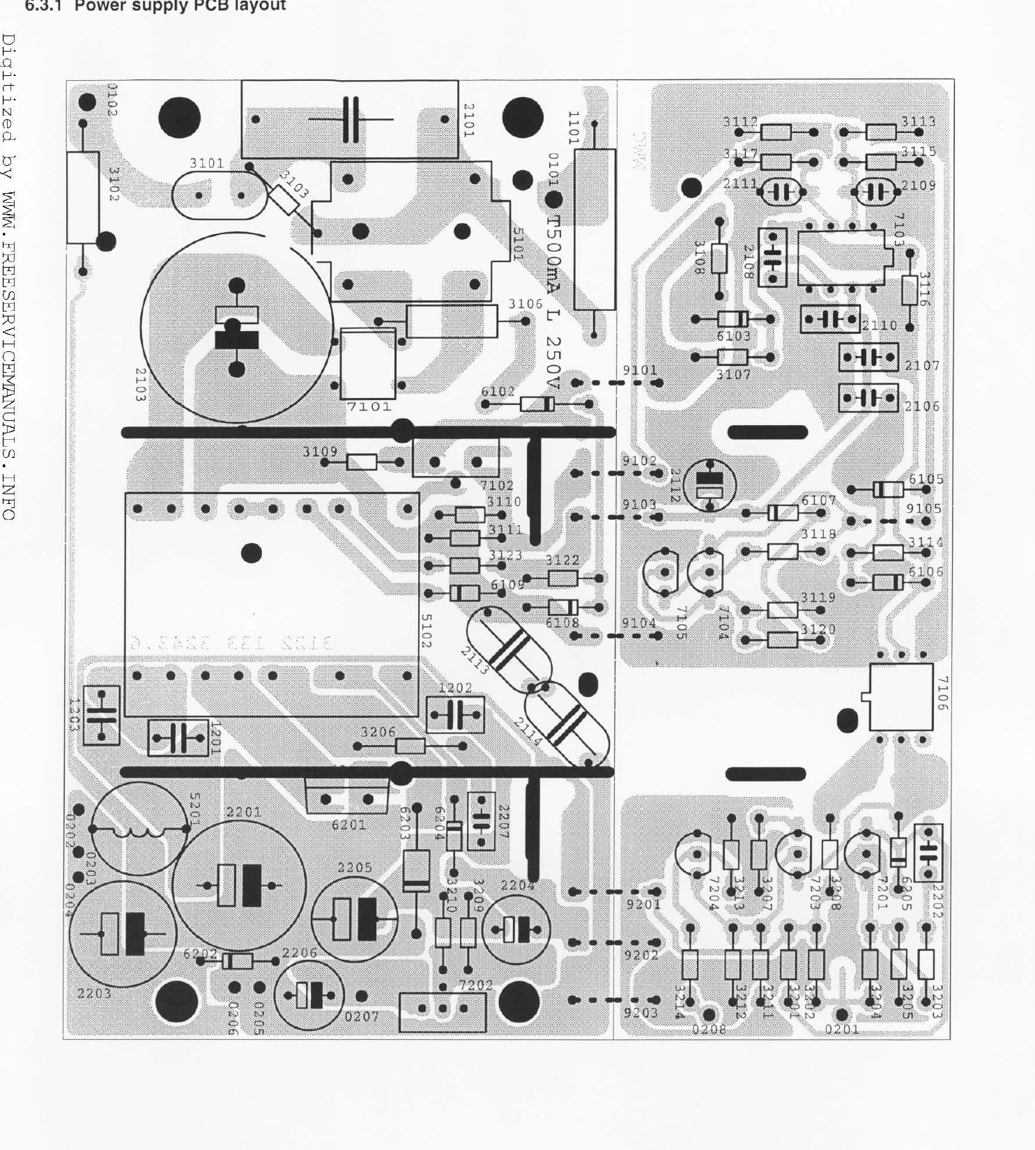
Component layout of the external power supply board for the Philips CDI 450, section 6.3.1 of the Philips service manual CDI 450/00/05/11/17 (page PCS 72 132). It shows every designator, including the 100 µF 400 V reservoir 2103, the secondary electrolytics 2201 to 2206, the mains fuse 1101 (marked T500mA L 250V) and the output fuses 1201 to 1203. Rendered at 200 dpi from the hosted manual.
Source
[edit | edit source]

Page 20 of File:Philips CDI 450 Service Manual.pdf. The New International CD-i Association (ICDIA), CD-i service manuals page, http://www.icdia.co.uk/svcmanuals/index.html, file cdi450.pdf (retrieved 2026-10-20). The scan carries the watermark of www.freeservicemanuals.info, which ICDIA names as the source of most of its service manual PDFs.
Author
[edit | edit source]

Philips Service & Support, Interactive Media Systems
Licence
[edit | edit source]

Copyright Philips. Hosted for preservation and repair reference, with the source cited.
File history
Click on a date/time to view the file as it appeared at that time.
| Date/Time | Thumbnail | Dimensions | User | Comment | |
|---|---|---|---|---|---|
| current | 00:20, 21 October 2026 | | 1,485 × 1,650 (1.21 MB) | Josh (talk | contribs) | Upload for the Philips CDI 450 pages |
You cannot overwrite this file.
File usage
The following 2 pages use this file:
