

File:Philips Odyssey 2100 main board.jpg
Summary
[edit | edit source]

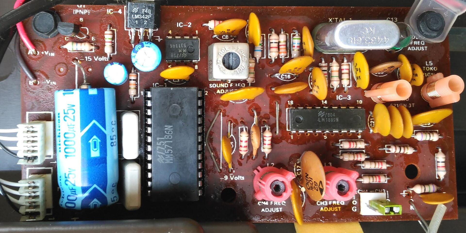
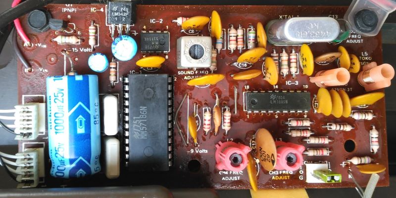
The component side of the main board of a Philips Odyssey 2100. Visible: the game chip IC-1 marked MM57186N in a socket, IC-2 MM53114N, IC-3 LM1889N, the regulator IC-4 marked LM342P, the PNP transistor Q1, the 1000 µF 25 V electrolytic (C1 in Philips's service manual), the crystal X'TAL 1 marked 4433.618, the sound coil marked SOUND FREQ ADJUST, the channel coils marked CH4 FREQ ADJUST and CH3 FREQ ADJUST, the CH4/CH3 channel switch, the supply terminals marked +VIN and -VIN, and test legends "-15 Volts" and "-9 Volts". The board's designators (Q1, X'TAL 1, L2, L3, L5) differ from the Philips service manual's (TS1, KT1, S2, S3, S5).
Source
[edit | edit source]

Wikimedia Commons, File:Philips Odyssey 2100 (4).jpg (retrieved 2026-10-20), from the blog Retro Ordenadores Orty.

Author
[edit | edit source]

José Antonio Ortigueira Amor, 29 November 2020.
Licence
[edit | edit source]

CC BY 4.0, as stated on the Commons file page.
File history
Click on a date/time to view the file as it appeared at that time.
| Date/Time | Thumbnail | Dimensions | User | Comment | |
|---|---|---|---|---|---|
| current | 23:47, 20 October 2026 | | 1,920 × 961 (391 KB) | Josh (talk | contribs) | Philips Odyssey 2100 board photo from Wikimedia Commons (CC BY 4.0) |
You cannot overwrite this file.
File usage
The following 2 pages use this file:
