

Philips Odyssey 2100
 | |
| A Philips Odyssey 2100 with its two controllers in their recesses | |
| Specifications | |
|---|---|
| Manufacturer | Philips |
| Type | Dedicated home video game console |
| Released | 1978[1][2] |
| CPU | None; game chip National Semiconductor MM57186 (IC1)[3] |
| Memory | — |
| Storage | — |
| Display | Colour, PAL, RF output on VHF channel E3 or E4[4][3] |
| Sound | Through the television[5][2] |
| Power | Mains adaptor, 24 V DC at the console's input[3] |
| OS / Firmware | — |
| Model no. | G 7513/00[2][6] |
The Philips Odyssey 2100 (type G 7513/00) is a dedicated home video game console that Philips sold in Europe from 1978. It plays 23 variants of six games in colour, with the sound coming from the television, and is built around National Semiconductor's MM57186 game chip.[1][5][3] It has no control panel: the game is chosen and reset with buttons on the two controllers.[5][2] Unlike the Philips Odyssey 2000, it has no Magnavox equivalent.[7]
History
[edit | edit source]Pong-Story describes the Philips Odyssey 2001 of 1977 and the Odyssey 2100 of 1978 as Philips consoles with no American equivalent, sold in countries including Germany, Belgium and Switzerland. Their case is similar to that of the Magnavox Odyssey 4000, and the controllers use the same boxes as the Odyssey 4000's with rotary knobs in place of the joysticks. The 2001 used National Semiconductor's MM-57105 chip with three games; the 2100 uses the MM-57186 and plays six game types.[7][1] Pong-Story names the unreleased Magnavox Odyssey 5000 as the 2100's closest American equivalent, though that console was designed around a different chip and played games the 2100 does not.[1]
The MM-57186N is the PAL version of National Semiconductor's MM-57106N. Pong-Story knows of only two consoles that used it: the Philips N30 (with its Radiola and Schneider equivalents) and the Odyssey 2100.[8] An owner's console bought in the Netherlands has the type label G 7513/00 and "MADE IN U.S.A." moulded into the bottom case. In Italy Philips's subsidiary Phonola sold the console in a beige case as the Phonola Teleflipper, type G 7513/02.[2][9][6]
Hardware
[edit | edit source]Chips and board
[edit | edit source]| Ref | Part | Function on the schematic | Philips 12NC |
|---|---|---|---|
| IC1 | MM57186 | Game chip: game reset and select, paddle generators, CPU, chroma, video and audio | 4822 209 10025 |
| IC2 | MM53114 | Clock generator | 4822 209 10023 |
| IC3 | LM1889 | Chroma modulator, RF modulator, 4.43 MHz, 5.5 MHz and channel oscillators | 4822 209 80387 |
| IC4 | LM342-12 | Regulator | 4822 209 80417 |
| TS1 | BC327 | Supply for the -8 V line | 4822 130 40854 |
| KT1 | 4.43 MHz crystal | Colour subcarrier for IC3 | 4822 242 70147 |
IC1 sits in a 24-pin socket.[3][10] On the schematic the clock generator IC2 takes its input through C9 from the 4.43 MHz oscillator at IC3 pin 17 and feeds IC1 pins 13 and 15.[3] The board is small: Pong-Story says it fills about a sixth of the case, and in the owner's photographs it is screwed to the top case in one corner, with the regulator on a metal bracket.[7][2][11]
The board's silkscreen does not use Philips's designators. It marks the PNP transistor Q1, the crystal X'TAL 1 and the channel coils L2 and L3, where the service manual has TS1, KT1, S2 and S3. It also has two test legends, "-15 Volts" and "-9 Volts", where the schematic gives -12 V and -8 V.[10][3]
Power
[edit | edit source]The console runs from a plug-in mains adaptor. Philips's schematic shows it, U1 (12NC 4822 691 10242), as a 220 V transformer and bridge rectifier, with 24 V DC across the console's input socket BU1, terminal A positive and terminal B negative.[3] The adaptor in the owner's photographs is model FW 8009, made in Germany, rated 220 V 50 Hz 6 VA in and 18.6 V DC 120 mA out, on a 3.5 mm jack plug.[12][2] The leaflet says the console works from the mains.[5]
Inside, C1 (1000 µF) smooths the input, the LM342-12 regulator IC4 sets a 12 V difference between line B and the circuit's ground, and TS1 with R1 (560 Ω) and R2 (1.5 kΩ) derives the -8 V line. The chips run from these negative lines.[3]
Controls
[edit | edit source]| Controller | Knob | Button |
|---|---|---|
| Left, blue | R26 (12NC 4822 101 20503). Moves the left bat. Turned fully left, it is switched out and the green knob works the play, for one-player games; on the schematic a contact at the end of R26's track joins the two controller inputs. | SK8, game select. Each press steps to the next game variant. |
| Right, green | R25 (12NC 4822 101 20502). Moves the right bat. | SK7, reset. Sets the score to 0:0; pressed with a bat turned to the top of the screen, it also makes that bat smaller. |
The controllers are fixed to the console by their cables and sit in recesses in the top case.[2] The bats move only up and down.[7]
Picture and sound
[edit | edit source]The picture is in colour. IC3, an LM1889, takes the colour-difference and video signals from IC1, modulates them on to a 4.43 MHz subcarrier and an RF carrier, and adds a 5.5 MHz sound carrier, so the sound comes from the television's speaker.[3][5] The leaflet sets the console to VHF channel 3 and says a dealer can change it to channel 4. The service manual's adjustments are for channels E3 and E4, and the board has a CH4/CH3 switch.[5][4][10] The volume is set on the television.[5]
Games
[edit | edit source]| Game | Variants | Numbers |
|---|---|---|
| Wipe-out (Abräumen, Jeu d'élimination) | 7 | 1 to 7 |
| Flipper | 7 | 8 to 14 |
| Tennis | 2 | 15 and 16 |
| Handball | 2 | 17 and 18 |
| Ice hockey | 2 | 19 and 20 |
| Football | 3 | 21 to 23 |
Wipe-out (game 1) comes up first when the console is switched on. Every game except wipe-out and flipper ends when a player reaches 15 points. The ball speeds up after a player has returned it four times and drops back to the starting speed with each new ball. The serve comes from the bat, and a bat held at the bottom of the screen does not serve.[5]
Maintenance and repair
[edit | edit source]Philips's service manual has three adjustments (the E3 and E4 channel oscillators, the 5.5 MHz sound oscillator and the 4.43 MHz colour oscillator), the schematic with DC voltages at the IC pins, the board layout and a short parts list, but no fault chart.[4][3]
- Philips Odyssey 2100 General Maintenance: opening the case, the adaptor, the controllers and the adjustments.
- Philips Odyssey 2100 Troubleshooting Guide: supply checks and pin voltages from the schematic.
- Philips Odyssey 2100 Capacitor Replacement Guide: the three electrolytic capacitors.
Documentation
[edit | edit source]The service manual CS43618 and the instruction leaflet are hosted and described on Philips Odyssey 2100 Documentation.[4][5]
Gallery
[edit | edit source]-
 Underside, with the type label G 7513/00 and the central fixing screw
-
 Bottom case removed: the board sits in one corner of the top case
-
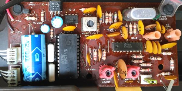 Main board, with IC1 (MM57186N) in its socket and the 1000 µF capacitor C1
-
 Adaptor FW 8009, 18.6 V DC 120 mA
-
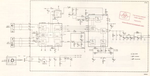 Philips's schematic, drawing 13978E2 (service manual CS43618, p. 3)


Related pages
[edit | edit source]- Philips Odyssey 2100 General Maintenance
- Philips Odyssey 2100 Troubleshooting Guide
- Philips Odyssey 2100 Capacitor Replacement Guide
- Philips Odyssey 2100 Documentation
- Philips Odyssey 2000, the earlier Philips console copied from the Magnavox Odyssey 2000
- Magnavox Odyssey 4000, whose case and controller boxes the 2100 shares
References
[edit | edit source]- ↑ 1.0 1.1 1.2 1.3 David Winter, Pong-Story, "Philips Odyssey 2100" (retrieved 2026-10-20): released in 1978; an improved version of the Odyssey 2001 using the National Semiconductor MM-57186N; six game types in 23 variants; the unreleased Magnavox Odyssey 5000 as its closest US equivalent, with a different chip.
- ↑ 2.0 2.1 2.2 2.3 2.4 2.5 2.6 2.7 José Antonio Ortigueira Amor, Retro Ordenadores Orty, "Philips Odyssey 2100 (1978)", in Spanish (retrieved 2026-10-20): the owner's console, type G 7513/00, serial 013900, bought in the Netherlands, marked made in the USA; controllers attached by cable and stored in recesses, each with a knob and a button; RF cable and a mini-jack socket for the external adaptor at the back; the bottom case removed by turning the central screw to the left, with the small board fixed to the top case; the MM-57186-N, LM1889N and MM53114N; colour picture and sound through the television in a working test; the adaptor rated 18.6 V 120 mA. Owner's hands-on description.
- ↑ 3.00 3.01 3.02 3.03 3.04 3.05 3.06 3.07 3.08 3.09 3.10 3.11 3.12 Philips, Service Manual Odyssey 2100, CS43618, p. 3 (sheet CS43619): schematic of the G7513 (drawing 13978E2) with the IC block names, pin voltages, the adaptor U1 and the supply; the board layout; the parts list with 12NC numbers for C1, C2, C5, C13, R25, R26, U1, KT1, IC1 to IC4, TS1, BU1, PL1 and the 24-pin IC socket. Hosted as File:Philips Odyssey 2100 Service Manual CS43618.pdf.
- ↑ 4.0 4.1 4.2 4.3 4.4 Philips, Service Manual Odyssey 2100, G7513, CS43618, p. 1: the console drawing with the four controls (1 game select; 2 left player and single-play switch; 3 reset and bat size; 4 right player and single player); service adjustments for channels E3 and E4 (S3 and S2), the 5.5 MHz oscillator (S1) and the 4.43 MHz oscillator (C13). Hosted as File:Philips Odyssey 2100 Service Manual CS43618.pdf.
- ↑ 5.00 5.01 5.02 5.03 5.04 5.05 5.06 5.07 5.08 5.09 5.10 Philips, Odyssey 2100 instruction leaflet, PDF p. 2 (lettered drawing A to F, screens of the 23 variants) and pp. 7 and 8 (German: controls, six game types, connecting to VHF channel 3 or 4, game order, the 15-point rule, bat size, speed-up after four returns, volume on the television, one-player play with the blue knob turned fully left, serving). Hosted as File:Philips Odyssey 2100 Instructions.pdf.
- ↑ 6.0 6.1 José Antonio Ortigueira Amor, photograph of the underside of a Philips Odyssey 2100, 29 November 2020, on Wikimedia Commons as File:Philips Odyssey 2100 (6).jpg (CC BY 4.0): type label G 7513/00, serial 013900. Hosted as File:Philips Odyssey 2100 underside.jpg.
- ↑ 7.0 7.1 7.2 7.3 David Winter, Pong-Story, "Other Magnavox Odyssey systems", section "Philips Odyssey in Europe" (retrieved 2026-10-20): the Odyssey 2001 (1977) and 2100 (1978) as Philips systems without US equivalents, sold in Germany, Belgium and Switzerland among others; the case similar to the Odyssey 4000's and the controller boxes the same, with knobs; the MM-57105 and MM-57186 chips; vertical player motion only; game selection by a controller button; the board occupying about a sixth of the case.
- ↑ David Winter, Pong-Story, "The General Instruments chips and others" (retrieved 2026-10-20): the MM-57106N of 1978 and its PAL version MM-57186N, with six game types in 23 variants, used only in the Philips N30 (and its Radiola and Schneider equivalents) and the Philips Odyssey 2100; the chip table listing the MM-57186N as the PAL version.
- ↑ José Antonio Ortigueira Amor, Retro Ordenadores Orty, "Consolas Magnavox, Philips y Phonola", in Spanish (retrieved 2026-10-20): the collection list with the Philips Odyssey 2100 (G 7513/00) and the Phonola Teleflipper (G 7513/02).
- ↑ 10.0 10.1 10.2 José Antonio Ortigueira Amor, photograph of the main board of a Philips Odyssey 2100, 29 November 2020, on Wikimedia Commons as File:Philips Odyssey 2100 (4).jpg (CC BY 4.0): board legends Q1, IC-1 to IC-4, X'TAL 1, CH4 FREQ ADJUST, CH3 FREQ ADJUST, SOUND FREQ ADJUST, the CH4/CH3 switch, "-15 Volts" and "-9 Volts"; IC1 in a socket. Hosted as File:Philips Odyssey 2100 main board.jpg.
- ↑ José Antonio Ortigueira Amor, photograph of a Philips Odyssey 2100 with the bottom case removed, 29 November 2020, on Wikimedia Commons as File:Philips Odyssey 2100 (5).jpg (CC BY 4.0). Hosted as File:Philips Odyssey 2100 opened.jpg.
- ↑ José Antonio Ortigueira Amor, photograph of the Philips Odyssey 2100 adaptor, 29 November 2020, on Wikimedia Commons as File:Philips Odyssey 2100 (2).jpg (CC BY 4.0): label "AC-ADAPTER", input 220 V 50 Hz 6 VA, output 18.6 V DC 120 mA, model FW 8009, made in Germany; jack plug. Hosted as File:Philips Odyssey 2100 AC adaptor FW 8009.jpg.