

Philips NMS 8245
 | |
| Drawing of the NMS 8245 from the cover of Philips's service manual. No freely licensed photograph of the machine has been found; a photograph is in the gallery below. | |
| Specifications | |
|---|---|
| Manufacturer | Philips (main board possibly made by Kyocera)[1] |
| Type | MSX2 home computer |
| Released | September 1987[1] |
| Intro price | ƒ1199 (Netherlands)[1] |
| CPU | Z80A[2] |
| Memory | 128 KB RAM, 128 KB video RAM, 48 KB ROM and 16 KB disk ROM[2] |
| Storage | Built-in 3.5-inch drive, 1 MB unformatted[2] |
| Display | Yamaha V9938[2] |
| Sound | PSG inside the S-3527 MSX-Engine[1] |
| Power | 220 V ±10 %, 50 Hz[2] |
| OS / Firmware | — |
| Predecessor | Philips VG-8235 |
| Model no. | NMS 8245/00, /16, /19[1] |
The Philips NMS 8245 is an MSX2 home computer that Philips released in September 1987. It was the last MSX machine Philips made and followed the VG-8235. The keyboard, the main board, the power supply and a double-sided 3.5-inch disk drive are all in one case.[1] Philips's service manual covers the /00 and /16 versions;[2] the MSX Resource Center also lists a French and Belgian /19 version with an AZERTY keyboard, and an Italian version sold as the Phonola NMS 8245.[1]
Specifications
[edit | edit source]| Item | Figure |
|---|---|
| Microprocessor | Z80A |
| Memory | 48 KB ROM, 16 KB disk ROM, 128 KB video RAM, 128 KB user RAM |
| Video processor | V9938 |
| MSX controller | S-3527 |
| Floppy disk drive | 3.5-inch, 1 MB |
| Interfaces | RF output (UHF channel E36), monitor output, SCART, cassette recorder, two joysticks, printer, two cartridge slots |
| Keyboard | QWERTY (/00 and /16) |
| Supply | 220 V ±10 %, 50 Hz |
[2] The case is printed "256 K RAM", which counts the video RAM with the 128 KB of main memory.[1] The first cartridge slot is at the top; the second, at the back, is closed by a cover and takes a cartridge holder supplied with the machine.[1]
Hardware
[edit | edit source]The main board (U100) carries the CPU, the S-3527 MSX controller, the V9938 video processor and both banks of memory. The parts list gives these main board ICs:[3]
| Position | Part | Notes |
|---|---|---|
| U1 | Z80A | CPU. The board photographed below has a Zilog Z0840004PSC. |
| U2 | M60003A | Marked Kyocera on the photographed board |
| U3 to U6, U16 to U19 | 81464-12 | Eight DRAMs: the 128 KB of main RAM and the 128 KB of video RAM |
| U7 | ROM/00/16 | System ROM, Philips part 4822 209 72581 |
| U8 | 2793 | Floppy disk controller |
| U11 | S-3527 | MSX controller |
| U13 | RP5C01 | Real-time clock, backed by BT1 |
| U15 | V9938 | Video processor |
| U9, U10, U12, U14, U20 | 74LS14, 7416, µPC311, 74LS04, MN1280 |
[3][4] The adjustment section of the manual names U8 as the floppy disk controller, U13 as the real-time clock and U15 as the video processor.[5]
The other assemblies are the power supply board (U101), the encoder unit (U102) with an MC1377 colour encoder and a 4.433619 MHz crystal, the LED panel (U103) with the reset switch and three lamps, and the floppy disk drive (U104, Philips part 4822 212 22883).[6]
Power supply
[edit | edit source]The supply is on its own board. A mains transformer feeds two windings. The first goes through F1 (T 3.15 A) to the bridge D1 to D4; the rectified rail feeds U1, an STR2005 switching regulator, for +5 V, and U2, a 7812, for +12 V. The second goes through F2 (T 315 mA) to the bridge D5 to D8 and U3, a 7812 wired so that its common terminal gives −12 V. The +5 V and +12 V outputs go to the disk drive through connector AC4 and, with −12 V, to the main board through AC5 and CN12.[7] The circuit is reproduced on the Philips NMS 8245 Capacitor Replacement Guide.
Disk drive
[edit | edit source]The drive is belt-driven: its parts list includes a belt (4822 358 20269) and a separate spindle motor (4822 535 92418). The service manual sets the spindle speed by the index period, 200 ±0.5 ms, with a screwdriver in an adjustment point on the spindle motor.[8]
Known problems
[edit | edit source]- The RTC backup battery BT1 is a NiCd cell inside a blue sleeve at the bottom right of the main board. The MSX Resource Center describes it as a GB150H-2, 2.4 V, 150 mA, and "prone to leaking"; owners on its forum advise removing it.[1][9] See the Philips NMS 8245 General Maintenance guide.
- Drive belts break. One owner found a broken belt and a loose drive connector in an NMS 8245 that answered "Disk offline".[10]
Documentation
[edit | edit source]Philips's service manual for the NMS 8245 is described on the Philips NMS 8245 Service Manual page. It has the adjustments, drive alignment, circuit diagrams, board layouts and parts lists.
Repair guides
[edit | edit source]- Philips NMS 8245 General Maintenance
- Philips NMS 8245 Troubleshooting Guide
- Philips NMS 8245 Capacitor Replacement Guide
Gallery
[edit | edit source]-
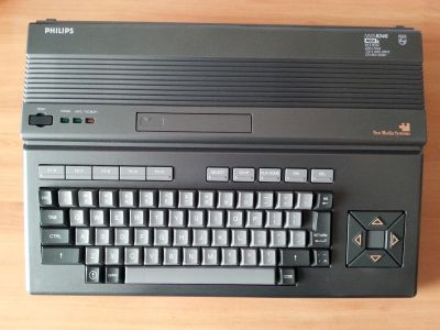 Top view, with the built-in drive and the lamp panel (MSX Resource Center wiki)
-
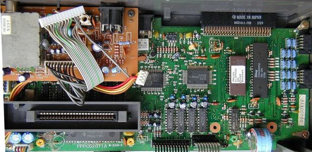 Main board with the case open (MSX Resource Center wiki)
-
 Power supply board and LED panel layout (service manual)


Related pages
[edit | edit source]- Philips NMS 8250, a separate-keyboard MSX2 from Philips with a different main board and power supply
- Philips NMS 8245 Service Manual
- Capacitor Failure Symptoms
- Battery Explosion, Capacitor or Corrosion Damage
References
[edit | edit source]- ↑ 1.00 1.01 1.02 1.03 1.04 1.05 1.06 1.07 1.08 1.09 Philips NMS 8245, MSX Resource Center wiki, 11 August 2026—link(accessed 2026-10-21) Community specification page: released September 1987 as the last Philips MSX and the successor to the VG-8235, with a fixed keyboard, a double-sided drive and no external drive connector; 128 KB of RAM in slot 3-2 (the "256 K" on the case adds the video RAM); models /00 (Netherlands and Belgium, QWERTY), /16 (Spain, QWERTY with ñ) and /19 (France and Belgium, AZERTY); sold in Italy as the Phonola NMS 8245; "several clues suggest that mainboard is manufactured by Kyocera"; launch price ƒ1199 in the Netherlands; Z80 from Zilog (Z8400APS) and Yamaha S3527 MSX-Engine; internal GB150H-2 NiCd battery for the RTC, 2.4 V, 150 mA, 17 mm pin spacing, "prone to leaking".
- ↑ 2.0 2.1 2.2 2.3 2.4 2.5 2.6 Philips, Service Manual, Home computer NMS8245/00/16, CS 11 823, order code 4822 727 16027, PDF page 1: specification. Hosted as File:Philips NMS 8245 Service Manual.pdf.
- ↑ 3.0 3.1 Philips, Service Manual NMS8245/00/16, PDF page 22: main printed board parts list. U100 main printed board 4822 219 81089; U1 Z80A; U2 M60003A; U3 to U6 and U16 to U19 81464-12; U7 ROM/00/16; U8 2793; U9 74LS14; U10 7416; U11 S-3527; U12 µPC311; U13 RP5C01; U14 74LS04; U15 V9938; U20 MN1280; X1 4 MHz; X2 32.768 kHz; X3 21.328125 MHz; BT1 Ni-Cd accumulator 4822 138 10235; RY1 relay; ST1 service jumper; VR1 50 kΩ and VR2 10 kΩ trimmers; TC1 and TC2 30 pF trimmers; tantalum capacitors C6, C9, C10, C13, C49, C52, C53 and C56, 22 µF 16 V. Note 1: install jumper JP2 and remove JP1 for the /16 version. Hosted as File:Philips NMS 8245 Service Manual.pdf.
- ↑ File:Philips NMS 8245 main board.jpg, photograph of an NMS 8245 main board uploaded to the MSX Resource Center wiki by Mars2000you, 10 March 2016. Read from it: a Zilog Z0840004PSC CPU, a gate array marked KYOCERA M60003A, the encoder and RF modulator board at the top left, and a blue cylindrical battery at the bottom right.
- ↑ Philips, Service Manual NMS8245/00/16, PDF page 2 (CS 11 824): caution notes and adjustments. VDP clock: frequency counter on 8-U15, adjust TC2 for 3,554,685 ±200 Hz. FDC read-pulse width: oscilloscope on 29-U8, 22-U8 to ground, adjust VR1 for 400 ±100 ns. FDC VCO: counter on 16-U8, 22-U8 to ground, adjust VR2 for 255 ±5 kHz. RTC clock: counter on 17-U13, adjust TC1 for 32.768 kHz. Encoder unit: counter on 17-U1, adjust TC1 for 4,433,619 ±20 Hz. Hosted as File:Philips NMS 8245 Service Manual.pdf.
- ↑ Philips, Service Manual NMS8245/00/16, PDF page 23: parts lists for the power supply (U101 4822 219 81091: U1 STR2005, U2 µPC7812HF, U3 MC7812CT, D1 to D4 S2V-10, D5 to D8 MPG06G, L1 coil, L2 180 µH), encoder unit (U102 4822 219 81092: IC1 MC1377, Q1 to Q4 2SC3330, C10 1 nF film, TC1 30 pF trimmer), LED panel (U103 4822 219 81118: LD1 yellow, LD2 and LD3 green, SW1 reset switch), various (BP1 transformer 4822 157 53332, DL1 400 ns delay line, X1 4.433619 MHz, modulator, CN2 monitor connector) and the floppy disk drive (U104 4822 212 22883). Hosted as File:Philips NMS 8245 Service Manual.pdf.
- ↑ Philips, Service Manual NMS8245/00/16, PDF page 13 (sheet CS 11 836): power supply U101 circuit diagram and the cartridge slot pin list; PDF page 28: capacitor voltage code (c 6.3 V, d 10 V, e 16 V, f 25 V). Hosted as File:Philips NMS 8245 Service Manual.pdf; the power supply part is reproduced as File:Philips NMS 8245 power supply circuit (service manual).png.
- ↑ Philips, Service Manual NMS8245/00/16, PDF pages 2 and 3: floppy disk drive alignment (dual-trace oscilloscope such as the PM3211, alignment disk 4822 395 30274, FDD test cartridge 4822 397 30171 started with CALL FDDTEST; radial alignment, track 00 sensor, azimuth within ±30′, index burst 400 ±200 µs, spindle speed by the index period of 200 ±0.5 ms at alignment point A); PDF page 5: FDD parts list (spindle motor 4822 535 92418, holder assembly, front, belt 4822 358 20269, complete PCB 4822 212 22884, bracket, stator and rotor of the stepper motor). Hosted as File:Philips NMS 8245 Service Manual.pdf.
- ↑ Any danger for Philips VG-8235 / NMS-8245 mainboards?, July 2017—link(accessed 2026-10-21) Replies of 26 to 31 July 2017: "In the 8245 you should remove the battery" (meits); the battery is "the big blue cylinder on the bottom-right part", removing it loses the RTC settings (screen width, colours, date), and the 8245's batteries seem more likely to leak than the VG-8235's (Louthrax); the blue cylinder holds two coin cells and must be desoldered (hardwaremaker).
- ↑ Broken drive on Philips NMS8245, March 2021—link(accessed 2026-10-21) Micha, 25 and 26 March 2021: the drive gave a short rattle at boot and "Disk offline" on FILES; when opened, the drive belt was broken and the connector to the drive was not plugged in properly.
