

National FS-5500
 | |
| FS-5500F2 with its trackball keyboard | |
| Specifications | |
|---|---|
| Manufacturer | Matsushita (National brand) |
| Type | MSX2 personal computer with superimpose and digitise |
| Released | December 1985 (Japan)[1] |
| Intro price | ¥188,000 (F1), ¥228,000 (F2)[1][2] |
| CPU | NEC D780C-1 (Z80A)[2] |
| Memory | 64 KB RAM, 128 KB video RAM[1] |
| Storage | One (F1) or two (F2) 720 KB 3.5-inch floppy drives[1][2] |
| Display | Yamaha V9938[1] |
| Sound | PSG inside the Yamaha S3527[1] |
| Power | AC 100 V ±10%, 50/60 Hz[2] |
| OS / Firmware | — |
| Model no. | FS-5500F1, FS-5500F2 |
The National FS-5500 is a desktop MSX2 computer that Matsushita sold in Japan from December 1985 under its National brand. It was built for video work: it can superimpose computer graphics on a video signal and digitise frames, and it has a front control panel for those functions and a keyboard with a built-in trackball. The FS-5500F1 has one floppy drive and the FS-5500F2 two; otherwise the two are the same.[1][2]
Models
[edit | edit source]| Model | Released | Price | Floppy drives |
|---|---|---|---|
| FS-5500F1 | 1 December 1985 | ¥188,000 | One, with a blanked bay for a second |
| FS-5500F2 | 21 December 1985 | ¥228,000 | Two |
[1][2] The front of both reads "National FS-5500"; the full model number is on the back.[1]
Hardware
[edit | edit source]The processor is an NEC D780C-1, the MSX-Engine a Yamaha S3527, the video chip a Yamaha V9938 and the floppy controller a Fujitsu MB8877A.[2] The machine is built from several boards. A main board, a video board, a ROM and RAM board, an expansion slot board and a separate power supply unit sit in the case, with the floppy drives at the front.[3]
| Board | Carries |
|---|---|
| Main board (marked DFUP0038ZA) | D780C-1, S3527, V9938 with heat sink, 128 KB VRAM, Ricoh RP5C01 clock (IC125), connectors for the video and memory boards |
| Video board | Superimpose and video circuits, alarm output and system terminals, keyboard layout and firmware switches |
| ROM and RAM board (DFUP0039ZA) | Five ROMs (OS1, OS2, AP1, HKN, FDC), two TMS4464 64K × 4 DRAMs for 64 KB of RAM |
| Expansion slot board (DFUP0040ZAG) | Three 50-way expansion slots, 20-way RAM expansion connector CN905, floppy connectors CN909 and CN910 |
| Power supply unit | Separate enclosed unit beside the drives |
Video functions and controls
[edit | edit source]The front control panel, behind a cover, has buttons and lamps for the superimpose and input modes, sliders for audio balance, fade level and digitise level, the two joystick ports, the trackball port switch with its lamps, and the headphone socket with its volume control. The keyboard's AVC key works with SELECT, INS, DEL and the function keys.[1][3] Two switches at the back select the keyboard layout (JIS or the Japanese syllabary layout) and turn the built-in firmware on or off. With the firmware on, BASIC gains the commands CALL SROMON, CALL SROMOFF and CALL SYSCON, thought to drive the alarm output and system terminals; what those terminals do has not been documented.[1][3] The supplied disk holds MSX-DOS 1 and Video Graphics, a drawing program with superimpose and digitise functions.[1]
Connections
[edit | edit source]The rear panel has a 21-pin RGB socket of the Japanese RGB21 type, which is not SCART; composite video and stereo audio inputs and outputs; an RF output with channel switch; printer and cassette connectors; the keyboard socket; three expansion slots; two AC 100 V outlets for a monitor; and the alarm and system terminals.[2][3][7]
Expansion
[edit | edit source]The three rear slots carry the standard MSX slot signals on a different connector, so an ordinary cartridge needs an adapter.[2][3] Matsushita's boards for them were the FS-BL8232 RS-232C board, the FS-BR1256 256 KB RAM board and the FS-BU9101 universal board. The FS-CR1008S cartridge, with 8 KB of battery-backed SRAM, stores firmware settings, software and clock data.[1]
Documentation
[edit | edit source]No service manual or circuit diagram has been found online. The MSX Resource Center gallery shows the FS-5500 and FS-BL8232 manuals, but no scan of them has been found online.[1]
Repair guides
[edit | edit source]- National FS-5500 General Maintenance
- National FS-5500 Troubleshooting Guide
- National FS-5500 Capacitor Replacement Guide
Gallery
[edit | edit source]-
 FS-5500F2 and keyboard
-
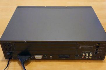 Rear panel
-
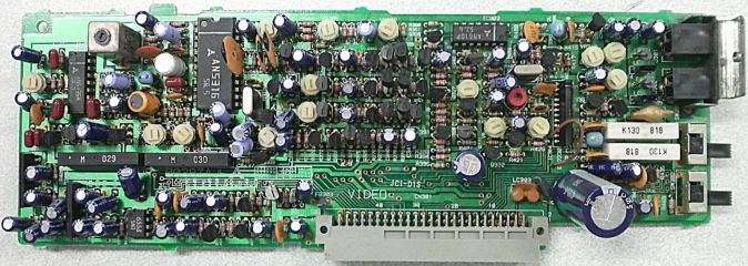 Video board
-
 ROM and RAM board
-
 Expansion slot board


Related pages
[edit | edit source]References
[edit | edit source]- ↑ 1.00 1.01 1.02 1.03 1.04 1.05 1.06 1.07 1.08 1.09 1.10 1.11 1.12 1.13 National FS-5500F1, MSX Resource Center wiki, 3 July 2026—link(accessed 2026-10-21) MSX2 with superimpose and digitise functions for the Japanese market, first shown at the Japan Electronics Show '85 (17 to 22 October); basically identical to the FS-5500F2 but with one floppy drive, with room to add a second (FS-FD352); the model name appears only at the back, with "National FS-5500" on the front. Two rear switches select JP50on or JIS keyboard layout and enable or disable the built-in firmware; extended audio and video control panel; built-in trackball ("Ball Mouse") with a front switch assigning it to joystick port 1, port 2 or neither; AVC key. Firmware, software and clock data can be saved on the FS-CR1008S cartridge (8 KB SRAM with a battery). Three expansion slots for FS-BL8232 RS-232C board, FS-BR1256 256 KB RAM board and FS-BU9101 universal board. Released 1 December 1985; ¥188,000; 64 KB RAM in slot 3-2; 128 KB VRAM; Yamaha V9938; PSG; Yamaha S3527; JP50on keyboard with JIS available by switch, numeric keypad; 720 KB 3.5-inch drive, reset button, eject button for each cartridge slot, headphone jack with volume control at the front, Kanji ROM level 1, MSX-DOS 1 and Video Graphics on disk, National BASIC firmware. The supplied disk cannot start MSX-DOS: CTRL+STOP at boot freezes the screen.
- ↑ 2.0 2.1 2.2 2.3 2.4 2.5 2.6 2.7 2.8 National FS-5500F2, MSX Resource Center wiki, 3 July 2026—link(accessed 2026-10-21) Identical to the FS-5500F1 apart from two floppy drives; released 21 December 1985; ¥228,000. Specifications: two front cartridge slots and two 3.5-inch drives; NEC D780C-1; Yamaha S3527 MSX-Engine; Fujitsu MB8877A floppy disk controller; the three rear slots have the standard slot pinout on a different connector, and the lowest has an extra 20-pin connector for RAM expansion; the keyboard holds an MN1550 that handles the trackball. Connections: RF output with channel switch; RCA audio and composite video input and output; RGB21 output (not SCART); keyboard; data recorder; Centronics printer port; two general ports with the trackball switch; two front cartridge slots; three rear expansion slots; headphone jack; alarm output terminal; system terminal (control output); mains plug (JIS C 8303, AC 100 V ±10%, 50/60 Hz); two AC 100 V outlets for a monitor; floating ground.
- ↑ 3.0 3.1 3.2 3.3 3.4 3.5 National FS-5500, USB Secret Base (up-c), 2010 to 2017—link(accessed 2026-10-21) Japanese description with annotated photographs. Rear panel: switched and unswitched AC 100 V outlets, fuse (125 V 3 A), power cable, keyboard connector, printer connector, earth terminal, 21-pin RGB connector, data recorder interface, three dedicated expansion slots, audio and video inputs and outputs, RF channel switch and output, alarm output terminal, system terminal (control output), keyboard layout switch, built-in software on/off switch. Front: cartridge slots 1 and 2 with eject buttons, reset switch, floppy drives A and B (B blanked on the F1), power switch and lamp, control panel cover. Control panel: superimpose buttons and lamps (computer, computer plus video, video), input buttons (RGB, video), mode buttons (halftone, computer cut, video audio cut, fade), audio balance, fade level and digitise level sliders, joystick ports 1 and 2, trackball port assignment switch and lamps, volume knob, headphone socket. Inside: floppy drives A and B (B normally not fitted on the F1), power supply unit, expansion slot board, memory board, video board. Sub-pages: the memory board carries the ROMs (MSX-BASIC, disk, built-in software, kanji font, single-kanji conversion) and two 64K × 4 DRAMs for 64 KB of main RAM; four 64K × 4 DRAMs give 128 KB of VRAM; the V9938 has a heat sink; the S3527 MSX-SYSTEM is the MSX1 part, extended with external circuits; the 50-pin connector on the main board takes the video board and the 64-pin connector the memory board; the expansion slot board has three 50-pin slots with standard MSX slot signals, a 20-pin connector CN905 said to be for RAM expansion, and 34-pin connectors CN909 and CN910 to the floppy drives; the video board carries the alarm output and system terminals and the keyboard layout and built-in software switches; with the built-in software switched on, CALL SROMON, CALL SROMOFF and CALL SYSCON(0,0) become available.
- ↑ MSX Resource Center wiki, File:Fs5500f1f.jpg, "National FS-5500 PCB", uploaded by Mars2000you on 13 September 2020 (the same photograph appears on USB Secret Base): main board marked DFUP0038ZA; NEC D780C-1; S3527 in a square flat package near the power connector; a long package under a metal heat sink; Ricoh RP5C01; a yellow cylindrical cell held by a cable tie; the video board standing at the left edge.
- ↑ File:National FS-5500 ROM and RAM board.jpg, uploaded to the MSX Resource Center wiki by Rderooy on 27 September 2016: board DFUP0039ZA with OS1 (DAS5500A1), HKN (DAS5500E1), AP1 (DAS5500C1), OS2 (DAS5500B1) and FDC (DAS5500F1) ROMs and two TMS4464-15NL DRAMs.
- ↑ File:National FS-5500 expansion slot board.jpg, uploaded to the MSX Resource Center wiki by Gdx on 26 February 2018: board DFUP0040ZAG with slot connectors CN904, CN906 and CN908, connector CN905, floppy connectors CN909 and CN910, and edge connectors CN911 and CN912.
- ↑ File:National FS-5500F2 rear panel.jpg, uploaded to the MSX Resource Center wiki by Gdx on 1 November 2023: AC outlets at the left, three expansion slot covers, keyboard lead, printer and cassette connectors, 21-pin RGB connector, audio and video sockets, RF output and switches.
