

Casio PV-7
 | |
| Black Casio PV-7 with the JOY PAD 1 cluster at the right | |
| Specifications | |
|---|---|
| Manufacturer | Casio |
| Type | MSX1 home computer |
| Released | 1984 (Japan) |
| Intro price | ¥29,800 |
| CPU | NEC D780C-1 (Z80A compatible), 3.58 MHz |
| Memory | 8 KB RAM, 16 KB VRAM |
| Storage | One MSX cartridge slot; cassette through the FA-32 interface |
| Display | Texas Instruments TMS9118NL |
| Sound | General Instrument AY-3-8910 |
| ROM | 32 KB MSX BASIC |
| Power | 10 V DC, 8 W, from the AC adaptor AD-4810 or the KB-7 |
| Dimensions | 307 × 210 mm; height 33 mm (front), 49 mm (rear) |
| Weight | 1560 g |
| OS / Firmware | — |
| Model no. | PV-7 BK (black), PV-7 RD (red) |
The Casio PV-7 is the first MSX computer made by Casio, sold in Japan from October 1984 at ¥29,800. It has 8 KB of RAM, one cartridge slot, no printer port and a chiclet keyboard, with an eight-way "JOY PAD 1" key cluster and two trigger keys, TR1 and TR2, that act as a joystick in port 1. It was made in black and red. The KB-7 expansion box adds RAM, two cartridge slots and a printer port, and powers the computer from its own supply.[1][2]
Specifications
[edit | edit source]| Item | Detail |
|---|---|
| CPU | Z80A compatible, 3.58 MHz (NEC D780C-1) |
| ROM | 32 KB MSX BASIC |
| RAM | 8 KB; 16 KB with the OR-208 or the KB-7; 32 KB with the KB-7 and an OR-216 |
| Video | TMS9118NL with 16 KB of video RAM; 32 × 24 text, 256 × 192 dots, 16 colours |
| Sound | 3 voices over 8 octaves, plus noise |
| Keyboard | JIS layout with kana in 50-sound order; joypad with 8 directions and 2 triggers |
| Size and weight | 307 × 210 mm, 33 mm high at the front and 49 mm at the rear; 1560 g |
| Power | AC 100 V through the adaptor; 8 W |
The main board is single-sided and carries many factory jumper wires. The CPU, BASIC ROM, an NEC µPD4168C-20 8 KB RAM, the TMS9118NL with two TMS4416 video RAMs and the AY-3-8910A sound chip are on the component side, and the board also carries a Fujitsu MB64H131 gate array.[4][5]
Connections
[edit | edit source]
- Right-hand side: the MT/IF socket for the FA-32 or FA-33 cassette interface (it is not a standard MSX tape socket), composite video, mono audio and the RF output to the switch box.[1]
- The two general-purpose ports, for joysticks such as the TJ-7.[3][4]
- Top: one cartridge slot. Its ±12 V, Sound IN, SW1 and SW2 pins are not connected, so cartridges that need ±12 V, such as the FM-PAC, do not work in it directly.[1][6]
- Underside: the expansion connector for the KB-7, and the RF channel switch.[1][7]
Power
[edit | edit source]The PV-7 has no internal mains supply. Its label rates it at 10 V DC, 8 W, from the AC adaptor AD-4810 or from the KB-7.[8] The AD-4810 is a 100 V adapter giving unregulated 10 V DC at up to 800 mA, centre negative, and Casio's manual says the PV-7 cannot be used outside Japan.[1][9] On the board, a 7805 regulator on an aluminium heatsink makes +5 V.[10] More detail is in the Casio PV-7 General Maintenance guide.
Related models
[edit | edit source]- The Casio PV-16 followed in 1985 as an improved PV-7, with 16 KB of RAM, a standard tape socket and a new main board.[11]
- Sanno sold a special version as the SPCmk-II.[1]
Documentation
[edit | edit source]- Casio PV-7 Instruction Manual: Casio's Japanese owner's manual, with the specifications and a troubleshooting chart.
No service manual or circuit diagram has been published; a request for one on the MSX Resource Center forum in 2024 went unanswered.[5]
Repair and maintenance
[edit | edit source]- Casio PV-7 General Maintenance
- Casio PV-7 Troubleshooting Guide
- Casio PV-7 Capacitor Replacement Guide
See also Capacitor Failure Symptoms.
Gallery
[edit | edit source]-
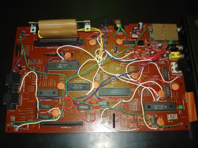 Main board, with factory jumper wires
-
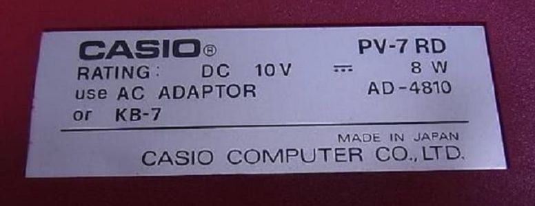 Rating label: 10 V DC, 8 W
-
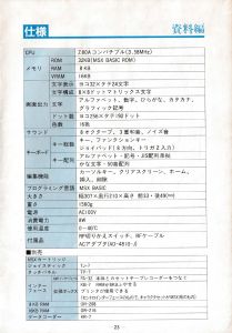 Specifications page of the manual


References
[edit | edit source]- ↑ 1.0 1.1 1.2 1.3 1.4 1.5 1.6 Casio PV-7—link(accessed 2026-10-21) First MSX computer released by Casio; 8 KB RAM and one cartridge slot, no printer port; chiclet keyboard; joypad keys labelled Joypad 1 and the TR1 and TR2 keys equivalent to a joystick in port 1; tape connector not standard, needing the FA-32 or FA-33 CMT interface; KB-7 expansion unit adds 8 KB RAM, two cartridge slots and a printer port and has its own power supply; AC power adaptor AD-4810; black (BK) and red (RD); year 1984-10-15; launch price ¥29,800 (computer), ¥14,800 (expansion unit); RAM 8 KB without KB-7 or 16 KB with KB-7, in slot 0; VRAM 16 KB; video TMS9118NL; audio PSG AY-3-8910; chipset: separate ICs with a Fujitsu MB64H131 gate array; Z80A from NEC (D780C-1); cartridge connector pins Sound IN, SW1, SW2, −12 V and +12 V not connected; power adapter input AC 100 V, 50/60 Hz, 16 VA, output up to 800 mA, unregulated DC 10 V, centre negative.
- ↑ 2.0 2.1 Casio, PV-7 取扱説明書 (instruction manual), printed page 23 (PDF page 25), 仕様: CPU Z80A compatible (3.58 MHz); ROM 32 KB (MSX BASIC ROM); RAM 8 KB; VRAM 16 KB; 32 × 24 characters; 256 × 192 dots; 16 colours; sound 8 octaves, 3 voices, noise; keyboard with joypad (8 directions, 2 trigger inputs), JIS layout with kana in 50-sound order; size 307 (W) × 210 (D) mm, height 33 mm at the front and 49 mm at the rear; weight 1560 g; power AC 100 V; consumption 8 W; operating temperature 0 to 40 °C; accessories RF switch box, RF cable, AC adaptor AD-4810-J. See Casio PV-7 Instruction Manual.
- ↑ 3.0 3.1 Casio, PV-7 取扱説明書, printed page 10 (PDF page 12): the KB-7 expansion box adds a printer connection, 8 KB of RAM and two slots, and the power adaptor is not needed when it is connected; PV-7 + 8 KB RAM (OR-208, for the PV-7) → 16 KB; PV-7 + KB-7 → 16 KB; PV-7 + KB-7 + 16 KB RAM (OR-216, for the KB-7) → 32 KB. See Casio PV-7 Instruction Manual.
- ↑ 4.0 4.1 Photograph of the PV-7 main board, component side (File:Casio PV-7 main board.jpg), uploaded to the MSX Resource Center wiki by Mars2000you on 8 February 2016: NEC D780C-1, Microsoft BASIC ROM 3256D19, NEC D4168C-20, TMS9118NL, two TMS4416 video RAMs, AY-3-8910A, silkscreen for the MB64H131, RF modulator, many jumper wires.
- ↑ 5.0 5.1 Repairing a Casio PV-7, February 2024 to December 2025—link(accessed 2026-10-21) lmanes, 10 February 2024: the PV-7 board is full of jumper wires and the PV-16 board design is much better; the VRAM chips are two TMS4416-12. st1mpy, 11 February 2024: the PV-7 PCB is single-sided with many jumper wires.
- ↑ MSX PV-7をFMPACが使えるように改造しました, 22 April 2019—link(accessed 2026-10-21) The PV-7 does not output +12 V and −12 V on the cartridge slot, so the FM-PAC's FM output did not work; the author added a dual ±12 V DC-DC boost module fed from the board's 5 V and wired its outputs to slot pins 48 (+12 V) and 50 (−12 V), and also connected pin 49 (SOUNDIN) to the PSG.
- ↑ Photographs of the PV-7's expansion slot and RF channel selector (files Pv7o.jpg and Pv7q.jpg) uploaded to the MSX Resource Center wiki by Mars2000you on 9 February 2016, https://www.msx.org/wiki/Casio_PV-7. Retrieved 2026-10-21.
- ↑ Rating label of a red PV-7 (File:Casio PV-7 rating label.jpg), uploaded to the MSX Resource Center wiki by Mars2000you on 26 June 2021: "RATING: DC 10V, 8 W; use AC ADAPTOR AD-4810 or KB-7".
- ↑ Casio, PV-7 取扱説明書, printed page 6 (PDF page 8): connect to a household AC 100 V outlet; it cannot be used abroad (外国では使えません). See Casio PV-7 Instruction Manual.
- ↑ Repairing a Casio PV-7 (page 2), 11 February 2024—link(accessed 2026-10-21) lmanes: after the repair, the remaining job was to replace the 7805 with a TRACO switching regulator to get rid of the aluminium heatsink; he had also upgraded the RAM to 16 KB and added the −12 V and +12 V lines.
- ↑ Casio PV-16—link(accessed 2026-10-21) The PV-16 is an improved version of the PV-7 with more RAM, a standard tape connector and a better mainboard.