

Philips VG-8020
 | |
| A silver VG 8020 at the Museum of Computing Instruments in Pisa | |
| Specifications | |
|---|---|
| Manufacturer | Kyocera, for Philips |
| Type | MSX home computer |
| Released | 1984 or 1985 (sources differ) |
| Intro price | ƒ1049 (Netherlands), 898 DM (Germany), 2990 Fr (France) |
| CPU | Z80A (NEC D780C-1 or Zilog Z8400APS) |
| Memory | 64 KB RAM, 16 KB video RAM, 32 KB ROM |
| Storage | MSX cartridges, cassette |
| Display | TMS9929A (/00); TMS9929A or TMS9129NL on later boards |
| Sound | YM2149 PSG (/00); PSG inside the S3527 MSX-Engine (later boards) |
| Power | 220 V ±10 %, 50 Hz, internal supply |
| OS / Firmware | — |
| Predecessor | Philips VG-8010 |
| Model no. | VG-8020/00, /19, /20, /29, /40 |
The Philips VG-8020 is an MSX1 home computer sold by Philips in the Netherlands, Belgium, France and Germany, and in Italy as the Phonola VG-8020. It was the third Philips MSX, after the Philips VG-8000 and Philips VG-8010, and was made for Philips by Kyocera.[1] Unlike its two predecessors it has a full-travel keyboard and its mains power supply inside the case.[1] Wikipedia gives 1984 as the year of introduction and a French price of 2990 Fr; the MSX Resource Center wiki gives 1985.[2] It was followed by the MSX2 NMS 8220.[2]
The case is marked "80K RAM 32K ROM". The machine has 64 KB of user RAM; the other 16 KB is the video RAM.[1][3]
Versions
[edit | edit source]| Version | Market | Main board | Keyboard | Video out |
|---|---|---|---|---|
| /00 | Netherlands, Belgium | First revision, separate chips | QWERTY | RF, composite, audio |
| /19 | France, Belgium | Second revision, S3527 | AZERTY | RGB |
| /20 | Netherlands | Second revision, S3527 | QWERTY | RF, composite, audio |
| /29 | Germany | S3527 | QWERTZ | RF, composite, audio |
| /40 | Netherlands | Third revision, S3527 | QWERTY | RF, composite, audio |
The /19 has a black case; the others are black and silver.[1] Philips's service manual covers the /00 only. No service manual for the /20 has been published, and the owner of a /20 on the MSX Resource Center forum used the NMS 8220 manual to work out its power supply connections.[4]
Hardware (VG-8020/00)
[edit | edit source]| Position | Part | Function |
|---|---|---|
| U3 | Z80A | CPU |
| U8 to U15 | 4864P-3 | 64 KB main RAM (eight chips) |
| U20 | HN613256PS41 | 32 KB MSX BASIC ROM |
| U18 | 8255AC-5 | Programmable peripheral interface (keyboard, cassette, slot select) |
| U24 | YM-2149 | Sound generator, joystick ports |
| U30 | TMS-9929A | Video display processor |
| U31 to U38 | 4816AP-7 | 16 KB video RAM (eight chips) |
| U23 | 74LS245 | Data bus buffer |
| U29 | 74LS273 | Printer data latch |
| U50 | NJM4558D | Audio mixing amplifier |
| U48 | UPC311C | Cassette input comparator |
| X1, X2 | 10.6875 MHz, 14.31818 MHz | VDP and system clock crystals |
Besides the main board, the /00 has three sub-assemblies: the power supply board U101, the PAL encoder U100 (an LVA510 with its own 4.433619 MHz crystal) and the RF modulator U102.[5][6] The later boards, marked MS28-PLM235BA0X on the /20 and MS28-PLM235CA0X on the /40 in the MSX Resource Center's photographs, use the S3527 MSX-Engine, a TMS9129NL video processor, an M38256-K5 BASIC ROM and two DRAM chips. The /20 board still carries a separate PAL encoder board; the /40 board does not.[1][7]
Power supply
[edit | edit source]The supply is a module (U101 on the /00, part 4822 216 92255) on its own board, fed by a mains transformer. An STK770 hybrid regulator and a 2SC2603 transistor give +5 V, set by the preset VR1; an AN7812 and a JRC7912 give +12 V and -12 V. The 5 V winding is fused at 1.6 A and each 12 V winding at 315 mA, all slow-blow.[5][8] Philips's NMS 8220 service manual lists a power supply of the same part number, 4822 216 92255, and the same transformer.[9]
Connections
[edit | edit source]| Connector | Notes |
|---|---|
| Mains | At the rear; the power switch is on the side of the case |
| TV (RF) | UHF channel E36, 75 Ω |
| Monitor | 8-pin DIN: +5 V, ground, audio, luminance, composite video and +12 V |
| Data recorder | 8-pin DIN: cassette out and in, and the remote motor contacts REM+ and REM- |
| Printer | 14-way Centronics-type, data bits 0 to 7, strobe and busy |
| Joysticks | Two 9-pin ports under the front edge, numbered 1 and 2 |
| Cartridge slots | Two, under a cover in the top of the case |
| Reset | Button at the rear |
The VG-8020/19 has an RGB output in place of the RF and composite outputs.[1] Pinouts are on the Philips VG-8020 Troubleshooting Guide.
Documentation
[edit | edit source]The Philips service manual for the /00 and the English installation manual are hosted on the wiki and described on Philips VG-8020 Documentation.
Maintenance and repair
[edit | edit source]- Philips VG-8020 General Maintenance: opening the case, cleaning the keyboard membranes, the 5 V and VDP clock adjustments.
- Philips VG-8020 Troubleshooting Guide: power supply faults, black screen, loss of colour, keyboard and cassette faults, connector pinouts.
- Philips VG-8020 Capacitor Replacement Guide: the electrolytic capacitors of the /00 from the service manual, and what is known for the later boards.
For general advice see Capacitor Failure Symptoms and Recommended Tools.
Gallery
[edit | edit source]-
 VG 8020/19, the black French version with an AZERTY keyboard
-
 VG 8020/20, as labelled by its exhibitor at RetroMadrid 2017
-
 Rear panel
-
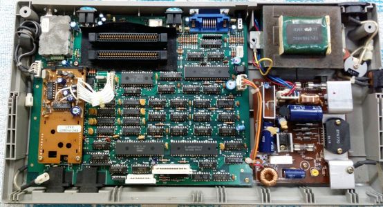 Inside a VG 8020/00: main board, PAL encoder board (left) and power supply board (right)
-
 VG 8020/20 main board
-
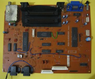 VG 8020/40 main board


Related pages
[edit | edit source]References
[edit | edit source]- ↑ 1.0 1.1 1.2 1.3 1.4 1.5 1.6 1.7 Philips VG-8020, MSX Resource Center wiki, 7 March 2026—link(accessed 2026-10-21) Community page: third Philips MSX1 after the VG-8000 and VG-8010; full-travel keyboard and internal power supply; 64 KB RAM, not the 80 KB printed on the case and box, which adds the video RAM; the /00, /19, /20, /29 and /40 versions with their regions, revisions, keyboards and video outputs; the /20 and /40 differ only by a few main board fixes; produced by Kyocera; sold as the Phonola VG-8020 in Italy; year 1985, launch prices 898 DM and ƒ1049; RAM in slot 3 on the /00 and slot 3-2 on the others; TMS9929A or TMS9129NL; YM2149 on the /00 and the S3527 MSX-Engine on the others.
- ↑ 2.0 2.1 Philips VG-8020, Wikipedia—link(accessed 2026-10-21) History: introduced in 1984 at 2990 Fr, manufactured by Kyocera, replaced by the NMS 8220; list of variants.
- ↑ 3.0 3.1 Philips, Service Manual, Home computer VG 8020/00, 4822 727 15228, PDF page 1, specification: Z80A; 32k ROM, 16k video RAM, 64k user RAM; TMS9929A; YM2149; RF output 75 Ω on UHF channel E36, monitor output, audio cassette recorder, 2 joysticks, 2 cartridge slots; 73-key QWERTY keyboard; 220 V ±10 %, 50 Hz. Hosted as File:Philips VG-8020-00 Service Manual 4822 727 15228.pdf.
- ↑ Philips VG8020/20 documentation needed, August 2024—link(accessed 2026-10-21) BartH: a dead /20 with the power light off and a humming transformer; fuses good; using the NMS 8220 service manual he found +12 V and -12 V present and +5 V missing; solved by resoldering the joints on the power board, which he thought had been cracked in transport. Jipe: the /20 uses the S3527 MSX-Engine and has no service manual of its own; the NMS 8220 manual is the nearest, and he thought the models share the power supply; for a missing +5 V check for DC across the 4700 µF capacitor, then the fuse and bridge rectifier, then adjust the VRT preset, and if that fails the STK770 is dead. Wierzbowsky suggested the RAM or the LVA510 encoder and had seen dead STK regulators.
- ↑ 5.0 5.1 5.2 Philips, Service Manual, Home computer VG 8020/00, 4822 727 15228, PDF page 7, electrical parts list (CS 100 730): main printed board ICs U1 to U53 with Philips part numbers, Q2 2SA720, Q3 2SC2603, C4 and C22 4.7 µF 25 V, TC1 25 pF trimmer, X1 10.6875 MHz, X2 14.31818 MHz; power supply U101 4822 216 92255 with U1 STK-770, U2 7812, U3 7912A, Q1 2SC2603, D1 to D4 S2V-10, ZD1 HZ2CL, R4 0.22 Ω 2 W, R8 56 Ω 3 W, VRT 500 Ω, C5 and C8 0.01 µF 50 V, L1 150 µH 3 A, T1 transformer 4822 146 21012; PAL encoder U100 4822 212 10216; RF modulator U102 4822 212 10215. Hosted as File:Philips VG-8020-00 Service Manual 4822 727 15228.pdf.
- ↑ 6.0 6.1 Philips, Service Manual, Home computer VG 8020/00, PDF pages 15 to 22, circuit diagrams: cartridge slots, CPU, memory and VDP (pages 15 to 18), keyboard, PPI, PSG, cassette, joystick and printer interfaces, power supply module U101 (pages 19 to 22). Hosted as File:Philips VG-8020-00 Service Manual 4822 727 15228.pdf.
- ↑ File:Philips VG-8020-20 main board.jpg and File:Philips VG-8020-40 main board.jpg, photographs of the /20 and /40 main boards uploaded to the MSX Resource Center wiki by Gdx on 7 March 2016. Read from them: board markings MS28-PLM235BA0X (/20) and MS28-PLM235CA0X (/40); TMS9129NL, M38256-K5 (Microsoft, 1985), Zilog Z80 CPU, DRAMs at U6 and U8; S-3527 outline on the component side; PAL encoder daughter board EMC-PX3607 on the /20 only.
- ↑ Philips, Service Manual, Home computer VG 8020/00, PDF page 22: circuit diagram of the power supply U101. Mains 220 V through line filter L100, a fuse and switch SW1 to T1; CN1 pins 4 and 5 feed bridge D1 to D4 (S2V10) through F3 (1.6 A T) to reservoir C2 (4700 µF) and the STK770 (U1) with TR1 (2SC2603), R4 (0.22 Ω), ZD1 and VR1 (500 Ω), output through L1 to J7 pin 1 (+5 V); CN1 pins 1 to 3 (pin 2 ground) feed bridge D5 (1B4B1) through F1 and F2 (315 mA T) to the AN7812 (U2, with R8 56 Ω across it) and JRC7912 (U3), outputs to J7 pins 2 (+12 V) and 3 (-12 V); the power LED on the main board is fed from +5 V at JN3 through R31 (220 Ω). See File:Philips VG-8020-00 power supply circuit diagram (service manual).png.
- ↑ Philips, Service Manual, Home computer NMS8220/00/16, PDF page 24, parts list: power supply U103 4822 216 92255, U1 STK-770, U2 7812, U3 7912A, Q1 2SC2603, D1 to D4 S2V-10, D5 1B4B1, D6 1S2076, ZD1 HZ2CLL, transformer T1 4822 146 21012. MSX Archive, https://www.msxarchive.nl/pub/msx/docs/service_manuals/philipsnms8220sm.pdf (retrieved 2026-10-21).
- ↑ Philips, VG 8020 MSX Computer installation manual (English pages), chapter 1 "Making the connections" (printed pages 2 and 3: most sockets at the rear; mains connector, power switch on the side, TV, monitor, data recorder and printer connectors and the reset button at the rear; joystick connectors 1 and 2 under the front) and appendix A (printed pages 50 to 52): mains connector, power switch, TV connector, monitor connector, data recorder connector, printer connector, reset button, joystick connectors; cartridge, data recorder, joystick, monitor and printer pinouts. Hosted as File:Philips VG-8020 Installation Manual.pdf.
