

MSX-Engine
 | |
| Yamaha S3527, the most widely used MSX-Engine | |
| Specifications | |
|---|---|
| Developer | Yamaha and Toshiba, to ASCII's MSX design |
| Manufacturer | Yamaha, Toshiba, Hitachi |
| Type | MSX system chip set on one integrated circuit |
| Package | 100-pin flat package (Yamaha S3527, S1985); 144-pin QFP (Toshiba T7937, T9769) |
| Voltage | +5 V |
| Used in | MSX1, MSX2, MSX2+ and MSX turbo R computers |
An MSX-Engine is a single chip that does the work of several of the separate chips in an early MSX computer. Depending on the type it holds the PPI that selects slots and scans the keyboard, the PSG sound chip that also reads the joystick ports, the DRAM and ROM control, the printer and cassette interfaces, and in some types the Z80 processor and the video chip as well.[1] Fewer chips meant a smaller board and a cheaper machine.[2]
For a repairer the useful questions are which engine a machine has, what it contains, and where to measure round it. The engine is a part, not a machine, so it has no maintenance or capacitor guides of its own; those are on each computer's pages.
Types
[edit | edit source]| Chip | Maker | Generation | Contains | Examples |
|---|---|---|---|---|
| T7775 | Toshiba | MSX1 | MSX1 system functions, probably including the PPI; no video or sound chip. Sources disagree on whether it contains the processor[3] | Sanyo MPC-200 |
| T7937, T7937A | Toshiba | MSX1 | Z80-type processor (TMPZ84C00A), T7766A PSG, T6950 video chip (TMS9918/9929 compatible), 8255-type PPI; a whole MSX1 apart from the memory[4] | Toshiba HX-51, Sakhr AX-170 |
| HD62003 | Hitachi | MSX1 | AY-3-8910-compatible PSG, DRAM controller, 8255-compatible PPI[5] | Casio MX-101 |
| S3527 (MSX-SYSTEM) | Yamaha | MSX1, also many MSX2 | YM2149 PSG, 8255-compatible PPI, DRAM and ROM control, printer interface; no processor or video chip[1] | Sony HB-10, Canon V-8, Philips VG-8020, Mitsubishi ML-G3, National FS-5500 |
| S1985 (MSX-SYSTEM II) | Yamaha | MSX2 | As the S3527, plus a memory mapper of up to 512 KB, an RP5C01A-compatible clock with battery-backed memory, 16 bytes of backup RAM and stereo PSG outputs[6] | Panasonic FS-A1, Sony HB-F1, Sony HB-F700, Sony HB-F900 |
| T9769, T9769A, B and C | Toshiba | MSX2, MSX2+, turbo R | Z80-type processor (3.58 MHz, switchable to 5.36 MHz on Panasonic MSX2+ machines), T7766A PSG, 8255-type PPI, MSX2 and MSX2+ functions[7] | Sanyo PHC-70FD Wavy, Panasonic FS-A1ST, Panasonic FS-A1GT |
Telling which engine a machine has
[edit | edit source]The chip is usually the largest square flat package on the main board, marked with the MSX logo and its type number.[8] Without opening the case, software can test for one: on machines with a Yamaha engine the PPI ports A8h to ABh also answer at ACh to AFh, and the video chip ports 98h to 9Bh answer at 9Ch to 9Fh.[1][6] Machines with a Toshiba T9769 add one wait cycle to every video chip access, which some timing-sensitive software notices.[7]
Measuring at the engine
[edit | edit source]Because the engine carries so many functions, a dead keyboard, a dead joystick port, missing sound and a machine that will not start can all lead back to it. Check its supply, clock and reset pins before suspecting the chip itself.
| Chip | +5 V | Ground | Clock | Reset |
|---|---|---|---|---|
| Yamaha S3527 | 40, 90 | 31; 6 for the PSG | 30 in (ϕIN), 29 out to the Z80 (ϕOUT) | 33 (RSTI) |
| Yamaha S1985 | 40, 90 | 31; 1 for the PSG; 86 for the clock back-up supply | Clock crystal on 88 and 89 | 85 |
| Toshiba T7937A | 18, 19, 90, 91 (cassette circuit 121) | 56, 57, 124, 125 (cassette circuit 123) | System crystal on 20 and 21; 134 gives the crystal frequency divided by six |
[1][6][4] On the S3527 the joystick inputs go straight to the chip: port 1 on pins 48 to 53, port 2 on pins 55 to 60, with strobe outputs on 54 and 61. The keyboard layout input is pin 63, and the Caps and Code LEDs are driven from pins 64 and 65.[1]
Known faults
[edit | edit source]Damaged joystick inputs
[edit | edit source]On the Philips VG-8235 the trigger line from joystick port 1 reaches the S3527 through a pull-up resistor and a small transistor. A VG-8235 whose first joystick read its trigger as permanently pressed had pin 52 of its S3527 (TRGA 1) sitting at about 0.7 V, even with the transistor in that line removed. The owner blamed a wrongly made network cable or a high voltage on the pin, and another member reported the same fault on a VG-8235 of his own.[9] The MSX Resource Center lists the controllers known to damage MSX ports, among them the Amiga mouse, Atari and Commodore paddles and Sega Master System pads.[10]
Replacing an engine
[edit | edit source]The engines are fine-pitch surface-mount packages of 100 or 144 pins.[1][4] In the forum thread above, replacement S3527s came from members' stock and from scrap boards. One member offered to cut the chip out of a scrap VG-8220 together with the board under it, so as not to bend or break its pins by desoldering, and warned that fitting one is a job for proper surface-mount rework equipment.[9] Before replacing an engine, rule out its supply and clock, the pull-up resistors and transistors between it and the ports, and the parts listed in the machine's own troubleshooting guide.
Documented modification
[edit | edit source]Machines with a Toshiba T9769 can be taken to 512 KB of RAM by lifting pins 51 and 52 and tying them to +5 V, lifting pin 50 for use as /CAS2 and pin 47 as address line A8, and fitting four 44256 memory chips on the bus. The method is credited to Tabajara Labs.[7]
Gallery
[edit | edit source]-
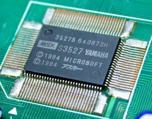 Yamaha S3527
-
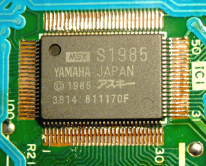 Yamaha S1985
-
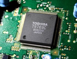 Toshiba T9769C
-
 Toshiba T7775 in a Sanyo MPC-200


References
[edit | edit source]- ↑ 1.0 1.1 1.2 1.3 1.4 1.5 Yamaha S3527, MSX Resource Center wiki, 8 May 2025—link(accessed 2026-10-21) The S3527 (also called MPC) is a chip set called MSX-SYSTEM, made by Yamaha for ASCII and Microsoft: a YM2149 PSG compatible with the AY-3-8910 (sound, joystick ports), a PPI compatible with the Intel 8255 (slot selection, keyboard, cassette interface), DRAM and ROM control and a printer interface, in 100 pins. Used in several MSX2 machines, where the clock and other MSX2 functions are separate ICs. Preceded by the X3527 in the Yamaha CX11. The three PPI ports (A8h to AAh) and the control port (ABh) are mirrored at ACh to AFh, which shows whether a machine has an MSX-Engine; VDP ports 98h to 9Bh are mirrored at 9Ch to 9Fh. Pinout: 4 PRISND (software sound), 5 SSGSND (PSG sound), 6 Vss (PSG ground), 29 ϕOUT (Z80 clock output), 30 ϕIN (clock input), 31 Vss, 33 RSTI (reset input), 40 VDD (+5 V), 48 to 53 joystick port 1 (FWD, BACK, LEFT, RIGHT, TRGA, TRGB), 54 STB 1, 55 to 61 joystick port 2, 63 JIS/50 keyboard layout input, 64 CAPS LED output, 65 CODE LED output, 90 VDD (+5 V), 91 BUSY, 92 to 99 printer data, 100 printer strobe. Computers listed with the S3527 include the Canon V-8, Mitsubishi ML-G3 and ML-G30, National FS-4500, FS-4700 and FS-5500F1/F2, Philips NMS 8245, NMS 8250, NMS 8280, VG-8020 and VG-8235, Sony HB-10, HB-501 and HB-F500, and Yamaha CX5MII and YIS-503II.
- ↑ MSX-Engine, Wikipedia—link(accessed 2026-10-21) Used for history only: an MSX-Engine combines the functions of several separate chips to reduce board space, power consumption and production cost; the first, the Toshiba T7775, worked beside a separate Z80-type processor, and most later engines include the processor; Yamaha engines were used mostly in Sony and Philips computers and Toshiba engines mostly in Sanyo and Matsushita (Panasonic and National) computers; from the MSX2+ onwards Toshiba made the engine chips.
- ↑ Toshiba T7775, MSX Resource Center wiki, 26 April 2025—link(accessed 2026-10-21) Chip set called MSX-ENGINE; CMOS chip with all MSX1 functions; likely includes the PPI; does not include the VDP or the sound chip. Used in a few MSX1 systems: Fenner FPC-500, Sanyo MPC-1, MPC-2 and MPC-200, probably the Sanyo PHC-25SK. The page also lists a Toshiba TMPZ84C00A Z80 clone at 3.58 MHz under "known features". Wikipedia, by contrast, describes the T7775 as working beside a separate Z80-type processor.
- ↑ 4.0 4.1 4.2 Toshiba T7937, MSX Resource Center wiki, 23 April 2025—link(accessed 2026-10-21) MSX-ENGINE for MSX1: Toshiba TMPZ84C00A Z80 clone at 3.58 MHz, T7766A PSG (AY-3-8910 compatible), T6950 rev. B VDP (TMS9918/TMS9929 compatible), TMP82C55A PPI; 31.45 × 31.45 × 4.1 mm QFP144; with memory chips for RAM, VRAM and ROM it makes a complete MSX1. Pins: XT1 and XT2 (21 and 20) for the system crystal; CLOCK (134) is the crystal frequency divided by six; VDD +5 V on 18, 19, 90 and 91; GND on 56, 57, 124 and 125; CVDD (121) and CGND (123) for the cassette circuit. Revisions T7937 and T7937A, the difference unknown. Used in the Al Fateh 100 and 123, Gradiente Expert Plus and DDPlus, Nikko PC-70100, Sakhr AX-170 and AX-230 (T7937A) and Toshiba HX-51 and HX-52 (T7937).
- ↑ Hitachi HD62003, MSX Resource Center wiki, 14 April 2023—link(accessed 2026-10-21) Chip set for MSX1: AY-3-8910-compatible PSG, DRAM controller, 8255-compatible PPI. Used only in the Casio MX-101.
- ↑ 6.0 6.1 6.2 Yamaha S1985, MSX Resource Center wiki, 2 May 2024—link(accessed 2026-10-21) Chip set called MSX-SYSTEMII, made by Yamaha for ASCII, similar to the S3527 with optional features: YM2149 PSG with stereo output (A centre, B left, C right), 8255-compatible PPI, DRAM and ROM control, printer interface, memory mapper up to 512 KB, Ricoh RP5C01A-compatible clock with 26 × 4 bits of RAM backed up by a separate battery, 8 × 16 bits of backup RAM, 100-pin flat package. Same PPI and VDP port mirrors as the S3527. Pins: 1 AVSS (PSG ground), 31 DVSS, 40 VDD (+5 V), 85 RESET, 86 BVSS (clock back-up supply), 88 XOUT and 89 XIN (clock crystal), 90 VDD (+5 V), 99 and 100 PSG left and right outputs. Computers listed include the Panasonic FS-A1, FS-A1F and FS-A1mkII, Sony HB-F1, HB-F1XD, HB-F1XV, HB-F700 and HB-F900, Sanyo PHC-77 and Yamaha YIS-805.
- ↑ 7.0 7.1 7.2 Toshiba T9769, MSX Resource Center wiki, 24 February 2026—link(accessed 2026-10-21) MSX-ENGINE: TMPZ84C00A Z80 clone at 3.58 MHz (switchable to 5.36 MHz on Panasonic MSX2+ machines), T7766A PSG, TMP82C55A PPI, MSX1 and MSX2 functions, MSX2+ functions in MSX2+ computers; QFP144. Four versions (T9769, A, B, C) and a predecessor T9763. Machines: Panasonic FS-A1FM (T9769), Sakhr AX-370 (T9769B), Sanyo PHC-55FD2 (T9763), Panasonic FS-A1FX and FS-A1WX and Sanyo PHC-35J, PHC-70FD and PHC-70FD2 (T9769A or B), Panasonic FS-A1WSX (T9769B or C), Panasonic FS-A1GT and FS-A1ST and Aucnet NIA-2001 (T9769C). Machines with a T9769 add one extra wait cycle to VDP I/O. The differences between revisions are not known, possibly related to the TC8566AF disk controller. 512 KB upgrade: lift pins 51 and 52 and connect them to +5 V, lift pin 50 and use it as /CAS2, lift pin 47 and use it as A8, and fit four 44256 chips on the bus (from Tabajara Labs).
- ↑ File:Yamaha S3527 MSX-Engine.jpg, File:Yamaha S1985 MSX-Engine.png and File:Toshiba T9769C MSX-Engine.jpg, photographs from Wikimedia Commons (CC BY-SA 3.0): the S3527 and S1985 are marked with the MSX logo, the type number and "YAMAHA"; the T9769C is marked "TOSHIBA T9769C".
- ↑ 9.0 9.1 VG8235 with broken S3527: any workaround?, December 2004 to January 2006—link(accessed 2026-10-21) Alexandre_Taito, 19 December 2004: on a VG8235 the first trigger of the first joystick is permanently pressed; from the joystick connector a pull-up resistor and a small transistor lead to pin 52 of the S3527, which stays at about 0.7 V, and removing it from the board does not help; suspects an improperly made MSX network cable or high voltage on the pin. Grauw, 15 January 2006: the same problem on one of his VG8235s. Sonic_aka_T: offers an S3527 cut from a scrap VG8220 board rather than desoldered, to avoid breaking its fine pins, and warns that soldering such an SMD part is not to be taken lightly.
- ↑ General Purpose port, MSX Resource Center wiki, 13 December 2025—link(accessed 2026-10-21) Devices that can damage an MSX general purpose port: Amiga mouse (pin 5 is button 2 on the Amiga, so pressing it shorts +5 V), Atari and Commodore paddles, FM Towns Marty pad and Sega SG-1000, Mark III and Master System pads (a button on pin 8 can damage that pin when it is high), DE9 RS-232C devices.