

Panasonic FS-A1FX
 | |
| Panasonic FS-A1FX. Photograph from the MSX Resource Center wiki; no freely licensed photograph has been found. | |
| Specifications | |
|---|---|
| Manufacturer | Matsushita Electric Industrial (Panasonic) |
| Type | MSX2+ home computer |
| Released | 21 October 1988 (Japan) |
| Intro price | ¥57,800 |
| CPU | Z80A in the Toshiba T9769 MSX-Engine, 3.58 MHz or 5.37 MHz |
| Memory | 64 KB RAM, 128 KB video RAM |
| Storage | Built-in 3.5-inch 2DD floppy drive (720 KB), MSX cartridges, cassette |
| Display | Yamaha V9958 |
| Sound | PSG in the T9769 |
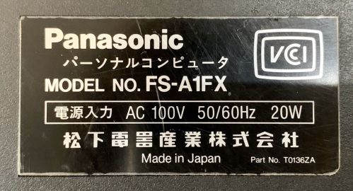
| Power | AC 100 V 50/60 Hz, 20 W, internal transformer |
| OS / Firmware | — |
| Model no. | FS-A1FX |
The Panasonic FS-A1FX is an MSX2+ computer made by Matsushita Electric Industrial and sold in Japan from 21 October 1988 at ¥57,800. It has a built-in 3.5-inch floppy drive, a front-panel switch that turns off the built-in menu software, a Ren-Sha Turbo slider for auto-fire and a CPU turbo mode of 5.37 MHz. It is the same machine as the Panasonic FS-A1WX without the MSX-MUSIC FM sound and the word processor, which is why the FS-A1FX lacks the WX's 取消 (cancel) and 実行 (execute) keys.[1][2]
Hardware
[edit | edit source]The FS-A1FX and FS-A1WX use the same main board, DFUP0250ZAU1a, with the parts for the FM sound, the word processor's SRAM and all but one ROM left unfitted on the FS-A1FX.[3][4][5] The main chips are the Toshiba T9769 MSX-Engine, which contains the Z80A, the Yamaha V9958 VDP with 128 KB of video RAM, the Toshiba TC8566AF floppy controller, a Mitsubishi M60014 gate array and a Sony CXA1145 video encoder.[4][1] The MSX Resource Center gives the gate array as M50014; the chip, BABAX's parts list and niga2 give M60014.[1][4][3]
Power
[edit | edit source]The FS-A1FX takes 100 V mains through a transformer inside the case and is rated 20 W.[2][4] On the main board, an MC34063 switching regulator makes +5 V from the transformer's two 12 V windings, and 78L12 and 79L12 regulators make ±12 V from a third winding.[6][7] Alexandre Souza of Tabajara Labs found the supplies of the FS-A1FX, FS-A1WX, FS-A1WSX, FS-A1ST and FS-A1GT to be the same design apart from the switching transistor; the Panasonic FS-A1GT Troubleshooting Guide covers the circuit in detail.[8]
Floppy drive
[edit | edit source]The drive is belt-driven and connects to the main board through a 24-way zero-insertion-force (ZIF) socket.[9] The MSX Resource Center gives the belt as rubber, 0.3 mm thick, 58 mm in diameter and 3 mm wide, the same size as the FS-A1F's.[1]
Backup cells
[edit | edit source]Two AA cells, type R6P (SUM-3), in a compartment in the base keep the clock and settings.[10][3]
Documentation
[edit | edit source]No Panasonic service manual for the FS-A1FX has been found. Because it shares its board with the FS-A1WX, two FS-A1WX documents cover it:
- File:Panasonic FS-A1WX schematic and parts list (BABAX, Rev 04a).pdf, BABAX's traced schematic of board DFUP0250ZAU1a, with a full parts list and notes on the FS-A1FX differences.
- File:Panasonic FS-A1WX circuit diagrams (pages 55 to 64).pdf, eight scanned pages of FS-A1WX circuit diagrams, including the power unit.
Repair guides
[edit | edit source]- Panasonic FS-A1FX General Maintenance
- Panasonic FS-A1FX Troubleshooting Guide
- Panasonic FS-A1FX Capacitor Replacement Guide
Gallery
[edit | edit source]-
 Main board DFUP0250ZAU1a during a recap; the power supply is at the left
-
 Rating label
-
 Power unit circuit from the FS-A1WX diagrams


Related pages
[edit | edit source]References
[edit | edit source]- ↑ 1.0 1.1 1.2 1.3 Panasonic FS-A1FX, MSX Resource Center wiki, 7 March 2026—link(accessed 2026-10-21) Community page: the same as the FS-A1WX but without MSX-MUSIC or the word processor; Ren-Sha Turbo auto-fire with a speed slider; black with red on the front; Japan; released 21 October 1988; ¥57,800; 64 KB RAM in slot 3-0; 128 KB VRAM; V9958; PSG in the T9769 (A or B); gate array given as Mitsubishi M50014; CPU turbo mode; 720 KB drive; firmware switch, reset and pause buttons; kanji ROM level 1 and Kanji BASIC; Cockpit firmware, skipped by holding DEL at boot or with the front switch; Z80A in the T9769, switchable from 3.58 MHz to 5.37 MHz through an I/O port (OUT 64,8: OUT 65,0 for 5.37 MHz, OUT 64,8: OUT 65,1 for 3.58 MHz); Toshiba TC8566AF floppy controller; main RAM expandable to 256 KB internally; MSX-MUSIC can be added by fitting the missing chips and a ROM; drive belt rubber, 0.3 mm thick, 58 mm diameter, 3 mm wide, sold as Panasonic FW-U1P501J; power plug for AC 100 V ±10 % 50/60 Hz; lithium or Eneloop backup cells recommended, alkaline advised against.
- ↑ 2.0 2.1 Rating label of an FS-A1FX: "MODEL NO. FS-A1FX, 電源入力 AC 100V 50/60Hz 20W, 松下電器産業株式会社, Made in Japan, Part No. T0136ZA". File:Panasonic FS-A1FX rating label.jpg, from the MSX Resource Center wiki (uploaded by Mars2000you, 19 September 2020).
- ↑ 3.0 3.1 3.2 BABAX, Panasonic MSX2+ FS-A1WX Schematic, revision 04a, 9 August 2014, with the parts list "FS-A1WX パーツリスト PARTS LIST" revision 02, 5 August 2014. File:Panasonic FS-A1WX schematic and parts list (BABAX, Rev 04a).pdf. A hand-traced community drawing, not a Panasonic document. The title block gives the board for both the FS-A1FX and the FS-A1WX as MAIN PWB No. DFUP0250ZAU1a, © Matsushita Electric Ind. 1988, and credits niga2 for FS-A1FX information; a note says that where a value reads "NC, 2.2k(FX)" the part is not fitted on the WX but fitted on the FX. Parts list: IC1 CXA1145M; IC3 M60014-0140FP; IC5 YM2413 (OPLL); IC7 MC34063P1; IC10 MN1280R; IC28 79L12; IC29 78L12; Q11 2SA1598; D1 and D2 GP30D; D8 SB540; R95 220 Ω; R96 0.2 Ω; R97 and R98 100 Ω; R99 2.09 kΩ; R101 1 kΩ; R113 22 Ω; R114 68 Ω; T1 transformer DDT5U7J02Z-W; V1 battery 1.5 V × 2; 30 electrolytic capacitors, listed on the Panasonic FS-A1FX Capacitor Replacement Guide.
- ↑ 4.0 4.1 4.2 4.3 FS-A1FX & FS-A1WX– up-c, 2011 to 2013—link(accessed 2026-10-21) In Japanese. Comparison of the two machines: the FS-A1FX has the YM2413 FM sound chip and its surrounding parts unfitted, and fitting them gives no FM sound without the ROM; one 2 Mbit (256 KB) ROM, where the WX has two 1 Mbit and two 4 Mbit ROMs and two 8 KB SRAMs; one long space key. Annotated board photographs: power transformer and power circuit; V9958 and 128 KB VRAM; DRAM main memory; Toshiba TC8566AF floppy controller; T9769 MSX-Engine; CMOS gate array M60014-0140FP; Sony A1145 (CXA1145) RGB encoder; separate address decoders for the WX and the FX; 24-way drive interface connector. Turbo: OUT 64,8: OUT 65,0 for 6 MHz (as written), OUT 64,8: OUT 65,1 for the normal clock.
- ↑ FS-A1FXの改造– niga2—link(accessed 2026-10-21) In Japanese. The FS-A1FX uses the same board as the FS-A1WX, so the FM sound parts are empty positions and only the LM324 op-amp is fitted; the gate array M60014 contains the FM I/O logic; the system ROM is a 2 Mbit mask ROM (23C2001); the video encoder CXA1145 supports Y/C output; a machine that switched on only sometimes, or switched off by itself, was not cured by replacing all the electrolytic capacitors: the tracks in the power supply area had lifted and the joints on the VDP and other thinly soldered joints had cracked, and after repairing and resoldering them it ran reliably.
- ↑ FS-A1WX circuit diagrams, figure 8, power unit (printed page 63). File:Panasonic FS-A1WX power supply circuit (figure 8).png, from File:Panasonic FS-A1WX circuit diagrams (pages 55 to 64).pdf. Power switch and transformer T1; four-pin connector; D1 and D2 into L1 and C57 and C34 (25 V 3300 µF); IC7 MC34063P1Q with Q11 (printed "2SA598"), R96 0.2 Ω, R97 and R98 100 Ω, R113 22 Ω, R114 68 Ω, timing capacitor C59 330 pF, catch diode D8 and inductor L5 to the +5 V (Vcc2) node with C53 (10 V 3300 µF); feedback R99 (printed 3.9 kΩ) and R101 (1 kΩ) from that node to IC7 pin 5, with R95 (330 Ω) and C54 (0.1 µF); then L6 and C70 (6.3 V 470 µF) to the +5 V rail; D7 and D6 from connector pin 4 to C36 and C35 (35 V 470 µF), IC29 78L12 (+12 V) and IC28 79L12 (−12 V), with C56 (0.1 µF) and C55 (50 V 1 µF). No crowbar thyristor is drawn.
- ↑ FS-A1FX/WX/WSX memory area PCB repair, March 2005 onwards—link(accessed 2026-10-21) Ten pages. Alexandre Souza (9 and 10 March 2005): an FS-A1FX board, in an FS-A1WSX case, whose RAM area had lost almost all its tracks to a failed 64 KB to 256 KB upgrade; repaired by cleaning the solder resist back with steel wool to see the tracks and rewiring with very thin wire; the transformer connector's pins 1 and 3 pass through diodes and join, and pin 4 feeds two diodes, one to a 78L12 and one, reversed, to a 79L12; running from a 24-0-24 V transformer the switching transistor became too hot. 22 March 2005: DaBest measured his FS-A1WX transformer: pin 1 12 V, pin 2 ground, pin 3 12 V, pin 4 17 V. Niles (18 January 2007): an FS-A1WSX supply destroyed by connecting a voltage converter the wrong way round.
- ↑ A fonte do MSX Turbo-R (e dos FX, WX e WSX tambem!)– Alexandre Souza, 9 July 2018—link(accessed 2026-10-21) In Portuguese. The power supplies of the Panasonic machines in the turbo R style of case (FS-A1FX, WX, WSX, ST and GT) are all the same, with equal or similar values, apart from the switching transistor; the 2SA1643 suits all of them; ±12 V from 7812 and 7912 type regulators fed through D7 (positive) and D6 (negative); +5 V from an MC34063 switching regulator; when it fails, suspect the MC34063 and the transistor first.
- ↑ Replace a MSX Turbo-R Diskdrive with a PC Drive– Erik Luppes, 9 June 2013—link(accessed 2026-10-21) For the Panasonic FS-A1FX, FS-A1WX, FS-A1WSX, FS-A1ST and FS-A1GT: a Samsung SFD-321B (older revisions with the high-density sensor) connected through an adapter board carrying the 24-pin ZIF socket desoldered from the faulty drive; mapping, 24-pin ZIF to 34-pin drive: +5 V 1 to the power connector, RDY 6 to 34, GND 7 to the power connector, Side Select 9 to 32, Read Data 11 to 30, Write Protect 12 to 28, Track 00 13 to 26, Write Gate 14 to 24, Write Data 16 to 22, Step 18 to 20, Direction Select 19 to 18, Motor On 20 to 16, Drive Select 0 22 to 10.
- ↑ Photograph of the FS-A1FX's battery compartment on the MSX Resource Center wiki, File:Fsa1fxh.jpg (uploaded by Mars2000you, 19 September 2020): two AA cells in the compartment; the label beside it gives R6P (SUM-3), 2 個, and the moulding beside the compartment gives SUM-3, UM-3 1.5 V, R6P, R6.