

Philips VG-8020 Capacitor Replacement Guide

The electrolytic capacitors of the VG 8020/00, the first version of the Philips VG-8020, can be read from the circuit diagrams in Philips's service manual, 4822 727 15228. Its parts list names only two of them, C4 and C22 on the main board (4.7 µF, 25 V).[1] No capacitor values have been published for the /19, /20, /29 and /40, which use a later main board; their electrolytics have to be read from the board.
Reading the voltage code
[edit | edit source]Philips's diagrams mark each electrolytic with a letter for its voltage rating. The key on page 10 of the VG 8020/00 manual lists a = 2.5 V, b = 4 V, c = 6.3 V, d = 10 V, f = 25 V, g = 40 V and h = 63 V, but leaves out e, which the diagrams use. The key in the NMS 8220 service manual gives e = 16 V.[2][3] The voltages in the tables below are decoded from those letters.
Power supply board (U101)
[edit | edit source]
| Ref | VG 8020/00 diagram | NMS 8220 diagram | Position |
|---|---|---|---|
| C2 | 4700 µF, f (25 V) | 4700 µF, g (40 V) | 5 V winding reservoir, after D1 to D4 |
| C3 | Faint on the scan, e (16 V) | 1000 µF, e (16 V) | +5 V output, where VR1 is set |
| C4 | 3300 µF, letter unclear | 3300 µF, f (25 V) | 12 V reservoir, at the input of the AN7812 |
| C6 | 1 µF, h (63 V) | 10 µF, h (63 V) | +12 V output |
| C7 | 220 µF, f (25 V) | 220 µF, g (40 V) | -12 V reservoir, at the input of the JRC7912 |
| C9 | 1 µF, h (63 V) | 10 µF, h (63 V) | -12 V output |
| C11 | 10 µF, h (63 V) | 10 µF, h (63 V) | At the STK770 |
The two manuals list a power supply with the same part number, 4822 216 92255, but their drawings of it differ: the NMS 8220 version adds a second filter coil and a diode, and some capacitor values and ratings are not the same.[1][5] Read every part on your own board before ordering. Where the board and the drawings differ in voltage, fit at least the highest of the ratings. C2, C4 and C7 sit on unregulated rectifier outputs and see more than their rail voltage.
Main board (VG 8020/00)
[edit | edit source]| Ref | Value | Voltage | Position |
|---|---|---|---|
| C35 | 470 µF | e (16 V) | +5 V where the supply enters, beside the power LED circuit |
| C22 | 4.7 µF | 25 V (parts list) | +5 V decoupling at the main RAM |
| C4 | 4.7 µF | 25 V (parts list) | +5 V decoupling at the video RAM |
| C36 | 22 µF | e (16 V) | Reset timing |
| C1 | 1 µF | e (16 V) | Cassette output |
| C7 | 10 µF | e (16 V) | Cassette input comparator U48 |
| C76, C77, C78, C79 | 10 µF | e (16 V) | Sound mixer U50: output, PSG, cartridge SOUND and BEEP inputs |
| C86 | 33 µF | e (16 V) | +5 V supply to the RF modulator |
| C87 | 100 µF | d (10 V) | Composite video feed to the RF modulator |
PAL encoder board (U100, VG 8020/00)
[edit | edit source]| Ref | Value | Voltage | Position |
|---|---|---|---|
| C18 | 100 µF | d (10 V) | +5 V supply to the LVA510 |
| C13 | 470 µF | c (6.3 V) | Composite video output |
| C2, C3 | 100 µF | d (10 V) | Input and output coupling of the luminance amplifier Q1 |
| C5 | 33 µF | d (10 V) | +5 V input at JN10 |
| C8 | 33 µF | d (10 V) | LVA510 pin 12 |
| C1 | 0.47 µF | g (40 V) | Input of Q2 (2SA564) |
| C6, C7 | 0.47 µF | g (40 V) | R-Y and B-Y input coupling |
The designators restart on each board, so C1, C4 and C7 each exist on more than one board. Mark which board a capacitor came from when you take it out.
Later boards (/19, /20, /29, /40)
[edit | edit source]-
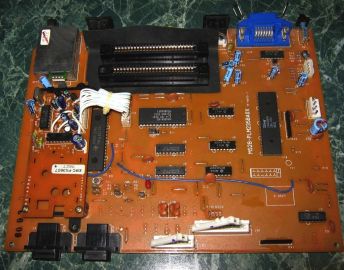 VG 8020/20 main board (MS28-PLM235BA0X), with its PAL encoder board at the left
-
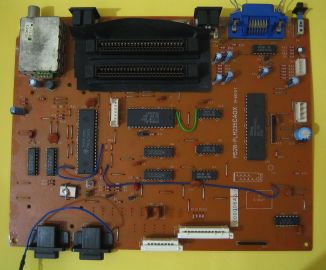 VG 8020/40 main board (MS28-PLM235CA0X)


The photographs of the /20 and /40 main boards show electrolytics at C13, C15, C19, C21 and C23 to C26, with a separate PAL encoder board on the /20 only. Their values cannot be read in the photographs.[8] An MSX Resource Center member thought the /20 and the NMS 8220 share their power supply, and the owner of a /20 in the same thread used the NMS 8220 manual to identify its supply rails.[9] Compare the supply board with the tables above before using them.
| Ref | Value | Voltage | Diameter × height | Board | Notes |
|---|---|---|---|---|---|
Which to replace first
[edit | edit source]The general advice on the MSX Resource Center forum is to replace the capacitors of the main power supply whatever their condition, to judge those in the audio and video circuits by the picture and sound, and to leave the small supply bypass capacitors round the board unless there is a reason.[10] On the VG 8020/00 that means:
- The supply board: C2, C4 and C7, then C3, C6, C9 and C11.
- C35 on the main board.
- The PAL encoder capacitors, if the picture is poor. A forum member who repaired a VG 8020/00 warns that the capacitors round the PAL encoder are critical, so fit exactly the values shown.[11]
- The audio coupling capacitors C76 to C79, if the sound is weak or distorted.
Procedure
[edit | edit source]- Unplug the computer and open it as described on Philips VG-8020 General Maintenance.
- Photograph each board, then each capacitor close enough to read its sleeve.
- Replace one capacitor at a time, with the stripe on the same side as the original.[10]
- On the supply board, check the joints round the regulators and the transformer connector while the board is out. Cracked joints there stopped a /20 from producing +5 V.[9]
- Before switching on, check that no loose lead or offcut can touch the main board. A loose keyboard ground lead touching U29 began a long run of faults on one recapped VG 8020/00.[11]
After the recap
[edit | edit source]- Switch on and set +5 V to 5.00 V across C3 with VR1.[12]
- Check +12 V and -12 V at cartridge slot pins 48 and 50, against ground at pin 41.[13]
- Check the picture in colour on both the RF and composite outputs, and the sound.
Remaining faults are covered in the Philips VG-8020 Troubleshooting Guide.
Related pages
[edit | edit source]- Philips VG-8020
- Philips VG-8020 General Maintenance
- Philips VG-8020 Troubleshooting Guide
- Philips VG-8020 Documentation
- Capacitor Failure Symptoms
References
[edit | edit source]- ↑ 1.0 1.1 1.2 Philips, Service Manual, Home computer VG 8020/00, 4822 727 15228, PDF page 7, electrical parts list: main board C4 and C22 4.7 µF 25 V (4822 124 10497), the only electrolytics listed; power supply U101 4822 216 92255 with C5 and C8 0.01 µF 50 V. Hosted as File:Philips VG-8020-00 Service Manual 4822 727 15228.pdf.
- ↑ Philips, Service Manual, Home computer VG 8020/00, PDF page 10, symbols used in circuit diagrams: miniature single electrolytic (-10 % +50 %) and single-ended electrolytic (±20 %); voltage note a = 2.5 V, b = 4 V, c = 6.3 V, d = 10 V, f = 25 V, g = 40 V, h = 63 V and higher codes, with no entry for e. Hosted as File:Philips VG-8020-00 Service Manual 4822 727 15228.pdf.
- ↑ Philips, Service Manual, Home computer NMS8220/00/16, PDF page 25, symbols used in circuit diagrams: the same key with e = 16 V. MSX Archive, https://www.msxarchive.nl/pub/msx/docs/service_manuals/philipsnms8220sm.pdf (retrieved 2026-10-21).
- ↑ Philips, Service Manual, Home computer VG 8020/00, PDF page 22, power supply U101 circuit diagram: C2 4700 µF (f), C3 (value faint, e), C4 3300 µF, C6 1 µF (h), C7 220 µF (f), C9 1 µF (h), C11 10 µF (h), ceramics C1, C10 and C12 100 nF and C5 and C8 10 nF; U1 STK770, U2 AN7812, U3 JRC7912, TR1 2SC2603, VR1 500 Ω; F1 and F2 315 mA T, F3 1.6 A T. Page 5, layout 37 540 B12, shows C1 to C12 on the board. Hosted as File:Philips VG-8020-00 Service Manual 4822 727 15228.pdf; see File:Philips VG-8020-00 power supply circuit diagram (service manual).png.
- ↑ 5.0 5.1 Philips, Service Manual, Home computer NMS8220/00/16, PDF page 7, power supply U103 circuit diagram: C2 4700 µF (g), C3 1000 µF (e), C4 3300 µF (f), C6 10 µF (h), C7 220 µF (g), C9 10 µF (h), C11 10 µF (h); with L2 and D6 (1S2076) in addition; PDF page 24 lists the supply as 4822 216 92255, the part number of the VG 8020/00 supply. MSX Archive, https://www.msxarchive.nl/pub/msx/docs/service_manuals/philipsnms8220sm.pdf (retrieved 2026-10-21).
- ↑ Philips, Service Manual, Home computer VG 8020/00, circuit diagrams: PDF page 15, reset circuit with C36 22 µF (e); page 16, C22 4.7 µF at the main RAM; page 17, C4 4.7 µF at the video RAM; page 18, RF modulator with C86 33 µF (e) on its +5 V and C87 100 µF (d) in the CVBS feed; page 20, cassette output C1 1 µF (e), cassette input C7 10 µF (e) at U48, mixer U50 with C76, C77, C78 and C79 10 µF (e); page 22, C35 470 µF (e) on +5 V at J7. Hosted as File:Philips VG-8020-00 Service Manual 4822 727 15228.pdf.
- ↑ Philips, Service Manual, Home computer VG 8020/00, PDF page 18, PAL encoder U100: IC2 LVA510 with C17 20 nF and C18 100 µF (d) on its supply; C13 470 µF (c) on the CVBS output; Q1 (2SC1634) with C2 and C3 100 µF (d); C1 0.47 µF (g) at the base of Q2 (2SA564), C6 and C7 0.47 µF (g) on the R-Y and B-Y inputs; C5 33 µF (d) and C4 20 nF on +5 V at JN10; C8 33 µF (d) at pin 12; X1 4.433619 MHz with trimmer C15 12 to 27 pF. Hosted as File:Philips VG-8020-00 Service Manual 4822 727 15228.pdf.
- ↑ File:Philips VG-8020-20 main board.jpg and File:Philips VG-8020-40 main board.jpg, photographs uploaded to the MSX Resource Center wiki by Gdx on 7 March 2016. Read from them: electrolytic capacitors at C13, C15, C19, C21, C23, C24, C25 and C26; a PAL encoder daughter board (EMC-PX3607) on the /20 only.
- ↑ 9.0 9.1 Philips VG8020/20 documentation needed, August 2024—link(accessed 2026-10-21) Jipe: the /20 uses the S3527 and has no service manual; see the NMS 8220 manual; he thought the models share the power supply. BartH used the NMS 8220 manual to measure his /20's supply.
- ↑ 10.0 10.1 Recap recommendations, June 2018—link(accessed 2026-10-21) Thread about recapping a Philips NMS 8250. RetroTechie, 23 June 2018: supply bypass capacitors spread over the board can often be removed without the machine stopping; capacitors in the audio and video circuits show their condition in the output; those in the main power supply are worth replacing regardless of condition; compare the service manual parts list with the board; replace capacitors one at a time. Wlcracks and RetroTechie recommend Rubycon, Chemi-Con, Nichicon or Panasonic parts from established distributors.
- ↑ 11.0 11.1 Philips VG8020 black screen problem...., October to December 2011—link(accessed 2026-10-21) JimGR's VG 8020/00 failed after a recap when a keyboard ground lead touched U29 with the machine running; Daemos: the capacitors round the PAL encoder are extremely critical.
- ↑ Philips, Service Manual, Home computer VG 8020/00, PDF page 2, adjustments: VR1 on the supply board for 5 V across the output (C3); TC1 for 445.32 kHz at pin 37 of U30. Hosted as File:Philips VG-8020-00 Service Manual 4822 727 15228.pdf.
- ↑ Philips, Service Manual, Home computer VG 8020/00, PDF page 15, cartridge slots: pins 45 and 47 +5 V, 48 +12 V, 50 -12 V, 41 and 43 ground. Hosted as File:Philips VG-8020-00 Service Manual 4822 727 15228.pdf.
