

File:Sharp MZ-40K schematic diagram.jpg
Summary
[edit | edit source]

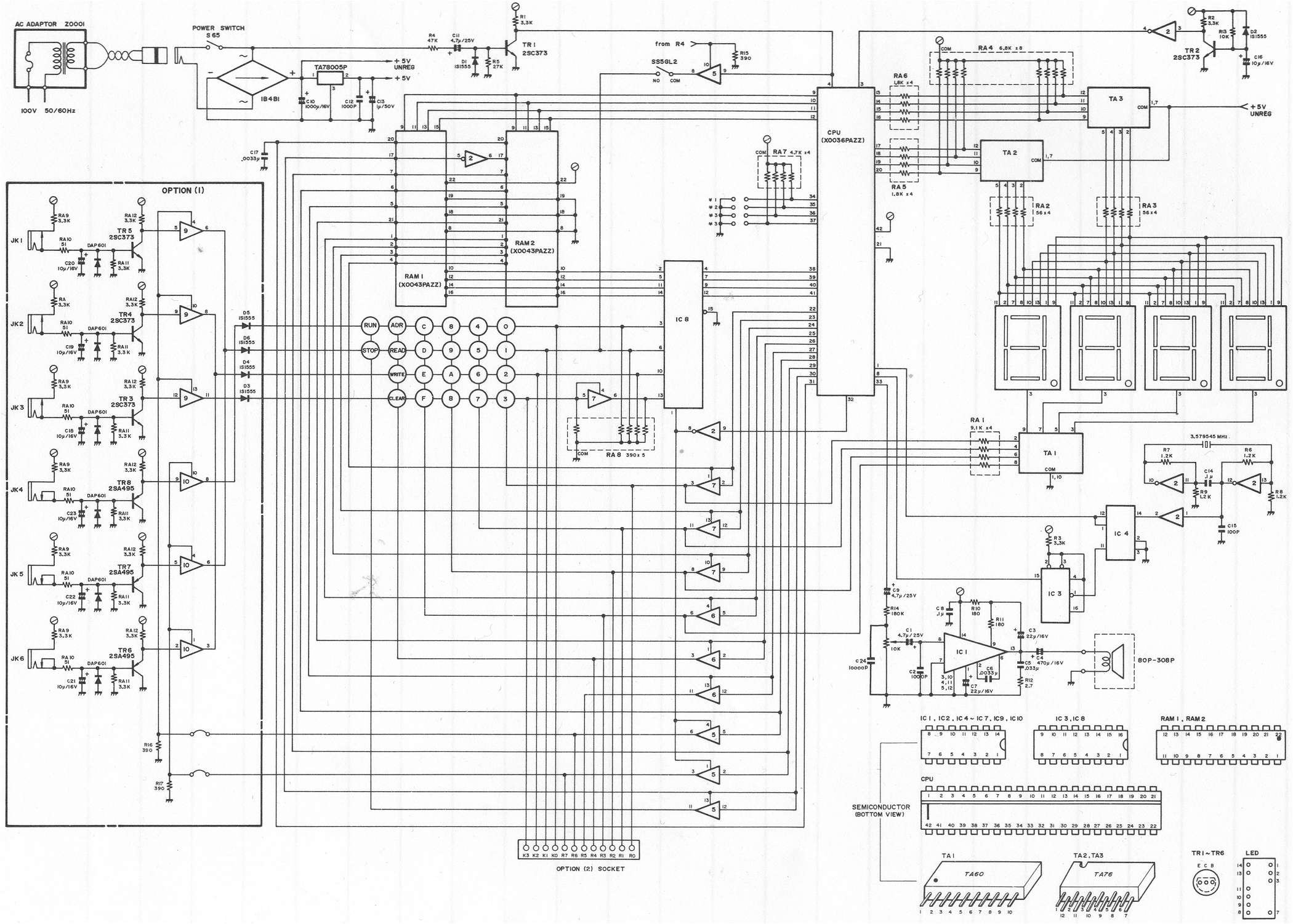
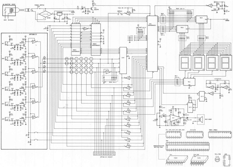
Sharp's schematic diagram of the MZ-40K, including Option 1 (sensor inputs JK1 to JK6) and the Option 2 socket. It shows the 100 V AC adaptor Z0001, the power switch, the 1B4B1 bridge, C10 (1000 µF 16 V) and the TA78005P regulator, the mains-frequency clock input through TR1, the MB8843 processor (X0036PAZZ), the two RAM chips (X0043PAZZ), the LED display drivers, the keypad, the crystal oscillator (3.579545 MHz) and the LM390 audio amplifier IC1 with its speaker.
Source
[edit | edit source]

https://www.sharpmz.net/mz-40/mz40kdiag.htm (SharpMZ, "Diagram MZ-40K"), image mz40kdiag.jpg, retrieved 2026-10-21.
Author
[edit | edit source]

Sharp Corporation (drawing); scan by SharpMZ.
Licence
[edit | edit source]

Copyright Sharp Corporation. Hosted for preservation and repair reference, with the source cited.
File history
Click on a date/time to view the file as it appeared at that time.
| Date/Time | Thumbnail | Dimensions | User | Comment | |
|---|---|---|---|---|---|
| current | 19:43, 21 October 2026 | | 2,100 × 1,502 (394 KB) | Josh (talk | contribs) | Upload for the Sharp MZ-40K pages |
You cannot overwrite this file.
File usage
The following 2 pages use this file:
