
IBM PC (5150) BIOS ROM Replacement

The BIOS of the IBM PC (5150) is a single 8 KB ROM in socket U33 on the system board. The four ROMs in U29 to U32 hold IBM Cassette BASIC, not the BIOS.[1] IBM's Technical Reference describes six ROM sockets for 8 KB devices, five of them filled, with the ROMs packaged in 28-pin modules with a 250 ns access time and a 375 ns cycle time.[2]
The U33 ROM has its own pinout, and a 2764 EPROM is not a pin-for-pin equivalent. Minuszerodegrees.net gives four reasons for replacing it: to swap it out and find whether it is faulty, because it is faulty, to upgrade to a later revision (the 10/27/82 BIOS is needed for an EGA card), and to fit a diagnostic ROM.[3]
Symptoms
[edit | edit source]- A board that appears dead. A faulty BIOS ROM is step 4 of minuszerodegrees' 11-step procedure for a dead 5150 or 5160 board, after visual inspection and reseating the socketed chips and before the power supply and clock checks; it suggests obtaining a known-good replacement.[4] Work through the troubleshooting guide's checks for no beep and no picture first.
- Limits of the two 1981 revisions: they recognise at most 544 KB of RAM and ignore the ROM on expansion cards, so EGA and VGA cards and hard disk controllers do not work. The 10/27/82 revision removes both limits.[1]
Tools and parts
[edit | edit source]- An IC extractor.
- An EPROM programmer that supports the chosen device, or a programming service. Minuszerodegrees keeps a list of people and companies who will program EPROMs, and some can supply programmed MCM68766 or 2564 chips.[5][3]
- A ROM image. Minuszerodegrees hosts 8 KB images of all four 5150 BIOS revisions; they contain the BIOS only, not Cassette BASIC.[6]
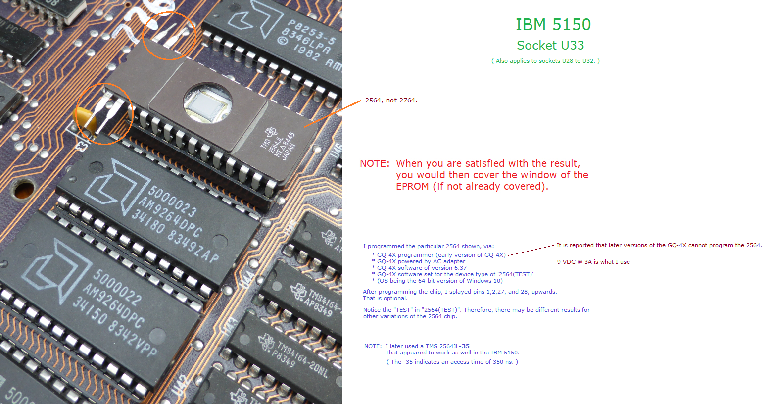
- One of the devices below, rated 250 ns or faster, the speed IBM used. Minuszerodegrees notes that a 350 ns part (a TMS2564JL-35) also worked in its 5150.[3][7]
| Device | Size | Fitting | Image to program |
|---|---|---|---|
| Motorola MCM68766 EPROM | 8 KB | Pin-equivalent for reading; fits U33 directly | The 8 KB image |
| Modern "drop-in replacement for the MCM68766" | Emulates an MCM68766 | As for the MCM68766 | |
| 2564 EPROM (2564, not 2764) | 8 KB | Equivalent for reading if pins 1, 2, 27 and 28 are not used after programming. Few programmers support the 2564. | The 8 KB image |
| 2764 or 27C64 EPROM | 8 KB | With an adapter | The 8 KB image |
| 27128 or 27C128 EPROM | 16 KB | With an adapter | The 8 KB image doubled |
| 27256 or 27C256 EPROM | 32 KB | With an adapter | The 8 KB image quadrupled |
| Winbond W27E257 EEPROM | 32 KB | With an adapter; the board cannot write to it, so program it in a programmer | The 8 KB image quadrupled |
Sources: minuszerodegrees.net.[3][6]
The adapter
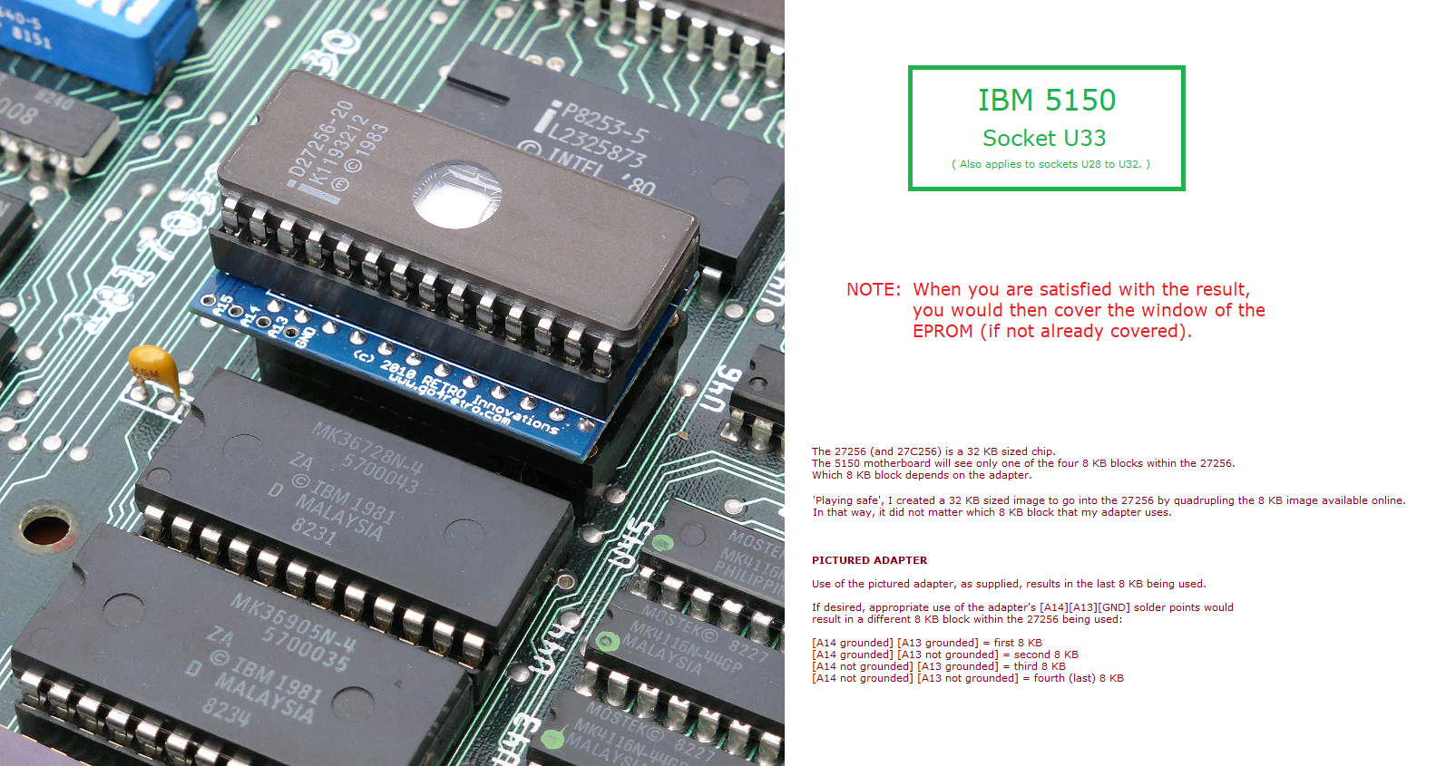
[edit | edit source]Minuszerodegrees uses an adapter sold as the "2364 Adapter", which takes 2764, 27128, 27256 and 27512 EPROMs (and their 27C equivalents) and the W27E257. The 2364 ROM is pin-compatible with the 5150 BIOS ROM for reading. As supplied, the adapter ties pins 1, 26 and 27 of its EPROM socket to Vcc through a pull-up resistor, so the board sees only the last 8 KB of a 27128, 27256, 27512 or W27E257. Either program the 8 KB image into that last block or fill the whole chip with copies of the image. The same adapter can be used in the Cassette BASIC sockets.[8][9] Other adapters exist but may need changes to work on a 5150.[8]

Procedure
[edit | edit source]Choose the revision
[edit | edit source]| Date | Part number | Boards | Notes |
|---|---|---|---|
| 04/24/81 | 5700051 | 16KB-64KB only | At most 544 KB of RAM; card ROMs ignored |
| 10/19/81 | 5700671 | 16KB-64KB only | The same two limits |
| 08/16/82 | 5000024 | May not have been released publicly. EGA and 5150-compatible VGA cards fail with the SW1 video switches on-on. | |
| 10/27/82 | 1501476 | Both boards | No 544 KB limit; card ROMs recognised. Needs all four RAM banks filled and set on the switches. |
Source: minuszerodegrees.net.[1]
- Read the part number on the chip in U33 to identify the revision fitted.[1]
- Choose the image. For a like-for-like replacement, use the same revision. The 10/27/82 revision is the one for EGA or VGA cards and hard disk controllers, and it runs on both boards.[1][3]
- Before fitting the 10/27/82 BIOS, fill all four system board RAM banks. Two bugs in that revision make the POST miscalculate the memory if fewer than four banks are fitted and set on SW1 and SW2.[10] See IBM PC (5150) RAM Replacement.
Prepare the chip
[edit | edit source]- Download the 8 KB image for the chosen revision.[6]
- For a 27128, double the image to 16 KB; for a 27256 or W27E257, quadruple it to 32 KB. With the 2364 adapter as supplied, an 8 KB image placed in the last 8 KB block also works.[6][8]
- Program the chip and verify it in the programmer.[3]
- For a 2564, minuszerodegrees bent pins 1, 2, 27 and 28 upwards after programming so that they do not enter the socket; it describes this as optional.[7]
- Once the chip has proved good in the machine, cover the window of a UV-erasable EPROM.[11]
Fit the chip
[edit | edit source]- Switch off and unplug the machine and remove the system unit cover; see the maintenance guide.
- Note which way round the chip in U33 is fitted, then lever it out with the extractor. The general method is in IC Removal and Socketing.
- Fit the replacement, or the adapter with its EPROM, in U33 the same way round. With the 2364 adapter in U33, minuszerodegrees warns that the adapter is a very close fit against the stock floppy drive.[8]
- If you have fitted the 10/27/82 BIOS to a 16KB-64KB board, set switch 5 of SW2 as well. The 1981 revisions read only switches 1 to 4; the 10/27/82 revision also reads switch 5, so the setting usually has to change. Minuszerodegrees' example for 128 KB is SW2 switches 1 to 8 set on, off, on, on, on, off, off, off, where the 1981 setting was on, off, on, on, off, off, off, off.[12][1]
Diagnostic ROM
[edit | edit source]A diagnostic ROM, such as Ruud's diagnostic ROM or the Supersoft/Landmark ROM, goes in the same socket in place of the BIOS ROM, using the same kind of device.[3] For RAM faults, minuszerodegrees recommends Ruud's ROM; see IBM PC (5150) RAM Replacement#Bank 0.
Testing
[edit | edit source]- Switch on. IBM's normal responses are a cursor after about four seconds, one short beep after the POST, and then the "IBM Personal Computer BASIC" screen, or the first diagnostics menu if the Advanced Diagnostics diskette is in the drive.[13]
- If the machine stays dead with the new chip, check its orientation, check that the image was doubled or quadrupled for the device used, and check that the device is one of those listed above.[3][6]
- After fitting the 10/27/82 BIOS, check the memory the POST counted from Cassette BASIC with
DEF SEG = &H40and thenPRINT PEEK(&H14)*256 + PEEK(&H13), which prints the total in KB.[10]
Related pages
[edit | edit source]- IBM PC (5150)
- IBM PC (5150) Troubleshooting Guide
- IBM PC (5150) Maintenance Guide
- IBM PC (5150) RAM Replacement
- IBM PC XT (5160) BIOS ROM Replacement
- IBM Cassette BASIC
- IBM PC 5150 Technical Reference
- IC Removal and Socketing
References
[edit | edit source]- ↑ 1.0 1.1 1.2 1.3 1.4 1.5 Minuszerodegrees.net, "IBM 5150 - BIOS Revisions": U33 holds the BIOS, U29 to U32 Cassette BASIC; the four revisions with part numbers, the boards each runs on, their limits and bugs.
- ↑ IBM, Technical Reference, 6322507, Revised Edition (April 1984), "System Board", p. 1-13: six ROM sockets for 8K devices, five filled with 40K of ROM, 28-pin modules, 250 ns access and 375 ns cycle time. Hosted as File:IBM PC 5150 Technical Reference.pdf.
- ↑ 3.0 3.1 3.2 3.3 3.4 3.5 3.6 3.7 Minuszerodegrees.net, "IBM 5150 - Substituting the U33 BIOS ROM": the U33 pinout and the 2764, reasons for substitution, the MCM68766, the drop-in MCM68766 replacement, the 2564, 27xxx EPROMs and the W27E257 with an adapter, and the 250 ns rating.
- ↑ Minuszerodegrees.net, "IBM 5150 and 5160 - Faulty motherboard symptom", step 4 "Faulty motherboard BIOS ROM?".
- ↑ Minuszerodegrees.net, "Some EPROM Programming Services".
- ↑ 6.0 6.1 6.2 6.3 6.4 Minuszerodegrees.net, "Images of BIOS ROM's for IBM 5150/5155/5160/5162/5170": 8 KB images of the four 5150 revisions, the EPROM options, and doubling or quadrupling the image for larger EPROMs.
- ↑ 7.0 7.1 Minuszerodegrees.net, 2564 in ROM socket U33, annotated photograph: pins 1, 2, 27 and 28 bent up after programming (optional), and a TMS2564JL-35 (350 ns) that also worked.
- ↑ 8.0 8.1 8.2 8.3 Minuszerodegrees.net, "IBM 5150 motherboard - Use of '2364 Adapter'": the EPROMs it takes, pins 1, 26 and 27 tied to Vcc, the last 8 KB block, use in U28 to U32, alternative adapters, and the close fit against the floppy drive.
- ↑ Minuszerodegrees.net, "IBM 5150 motherboard - ROM's - Adapter choice": the bought 2364 adapter and a home-made alternative.
- ↑ 10.0 10.1 Minuszerodegrees.net, "IBM 5150 - 10/27/82 BIOS - Problem of less than 4 banks of RAM": the two bugs and the BASIC statements that read the memory size.
- ↑ Minuszerodegrees.net, 27256 and adapter in ROM socket U33, annotated photograph. Hosted here as File:IBM 5150 27256 EPROM on adapter in socket U33 (minuszerodegrees).jpg.
- ↑ Minuszerodegrees.net, "IBM 5150 - BIOS upgrade on 16KB-64KB motherboard - SW2 example".
- ↑ IBM, Hardware Maintenance and Service, 6025072 (August 1981), PIC 010 "Start", p. 010-5: normal responses at power-on. Hosted as File:IBM PC 5150 Hardware Maintenance and Service (August 1981).pdf.