

Osborne Vixen
 | |
| Osborne Vixen (Osborne 4) | |
| Specifications | |
|---|---|
| Manufacturer | Osborne Computer Corporation |
| Type | Portable computer |
| Intro price | US$1,298 |
| CPU | Zilog Z80A at 4 MHz |
| Memory | 64 KB DRAM (eight 4164), 4 KB EPROM |
| Storage | Two half-height double-sided, double-density 5.25-inch drives |
| Display | 7-inch amber CRT, 80 × 24 characters |
| Sound | Piezo audio alarm |
| Ports / interface | RS-232-C serial (8251A); parallel port programmable as IEEE-488 or Centronics (8155); composite video |
| Weight | 22 lb |
| OS / Firmware | CP/M |
| Predecessor | Osborne Executive |
| Model no. | Osborne 4 Vixen, part 2P40064-02 |
The Osborne Vixen, sold as the Osborne 4, is a compact CP/M portable computer from Osborne Computer Corporation of Fremont, California, with a 7-inch amber screen and two half-height drives. Osborne's sales brochure, which is undated, priced it at $1,298, and $2,798 with a factory-fitted external 10 MB hard disk.[1] Osborne's technical description of the machine, the Osborne 4 Theory of Operation Manual, is dated August 1985 and gives its weight as 22 lb.[2]
Specifications
[edit | edit source]The brochure gives two double-sided, double-density, half-height 400K drives, a 7-inch amber monitor, an 80-column, 24-line display with 8 × 10 dot characters, serial and parallel ports, CP/M, and a 90-day warranty. The bundled software included WordStar, MailMerge, SuperCalc 2, MBASIC, Osboard, TurnKey, Desolation and Media Master, which reads and writes diskettes for other computers including the IBM PC.[1]
Architecture
[edit | edit source]The 1985 Theory of Operation Manual describes two boards, a system board and an I/O board.[2]
- System board: a 23.9616 MHz oscillator, divided to a 12 MHz dot clock, the 4 MHz CPU clock, a 2 MHz clock for the serial controller and a 1 MHz clock for the disk controller; the Z80A; a single 2732 4K monitor ROM at 4C; eight 4164 64K×1 DRAMs, of which 60K is for general use and 4K is the screen buffer; an 8155 for keyboard control; a 1797 floppy disk controller; and the display controller with a 2716 character generator ROM at 1J.
- I/O board: an 8155 whose two 8-bit ports form a parallel interface that can be programmed for IEEE-488 or Centronics, and an 8251A USART for the RS-232-C port.
The 1797 supports the Osborne 1 single- and double-density formats and IBM PC, DEC VT180, Xerox 821 and Cromemco formats. The manual's Table 9-1 gives 100K (92K for CP/M) in Osborne single density and 200K (185K) in Osborne double density.[2] The brochure describes the drives as 400K.[1]
The March 1983 engineering drawings
[edit | edit source]Osborne's engineering drawing package dated March 1983 lists an earlier design of the boards.[3] Its main logic list (revision 2.1) has a Z80A at C4, a 1793 disk controller at H12, eight 4164 DRAMs at F1 to F4 and G1 to G4, two 2114 1K×4 static RAMs at E5 and E6, three 2732 EPROMs at F11, G7 and H3, an 8155 at H7, a 23.9616 MHz crystal at Y1 and a piezo alarm at A1. That is a different arrangement from the 1985 manual's single ROM at 4C, 1797 controller and 2716 character generator, so the 1983 list should not be taken as the production board without checking against the board itself.
The 1983 I/O board list (revision 1.1) has an 8155 at C7, an 8251A at C3, a 1488 driver at A1, 1489A receivers at A2 and A3, 7406 and 7407 open-collector buffers, a 25-pin RS-232 connector at J1 and a 24-pin IEEE-488 connector at J2.[3] The hosted I/O board photograph shows the connector position silkscreened "IEEE488".
The monitor sub-assembly drawing names a Kaga monitor with V-LIN, V-HEIGHT, V-HOLD and VIDEO CENTER adjustments.[3]
Power supply
[edit | edit source]No Osborne specification for the Vixen supply's voltages or currents is hosted here. Sheet 1 of the hosted Vixen schematic set is Osborne's drawing of an Astec switching supply (drawn 10 August 1983) with outputs labelled +12V1, +12V2, +5V and −12V, a crowbar SCR and zener on the +5 V output, and designators but no component values.[4] The Osborne 1 and Executive supply limits belong to those machines and should not be applied to the Vixen.
Capacitors
[edit | edit source]The 1983 main logic list has five aluminium electrolytics: C1 and C2 at 47 µF 10 V, C3 and C4 at 68 µF 10 V, and C7 at 10 µF 10 V. The 1983 I/O board list adds C1 at 22 µF 16 V.[3] The schematic in the same package differs at C2 to C6, putting C2 and C4 on the −12 V and +12 V inputs, and the revision C board renumbers its capacitors; details are on the Osborne Vixen Capacitor Replacement Guide.
Documentation
[edit | edit source]| Boards | Documents |
|---|---|
  |
Osborne 4 Theory of Operation Manual, 1985 Osborne Vixen Engineering Drawings Mar83: assembly drawings and the 1983 lists of materials Vixen schematic set: 13 sheets Sales brochure and order form |
There is no Osborne field service manual or troubleshooting chapter for the Vixen among these documents.
Gallery
[edit | edit source]-
 Osborne Vixen, front
-
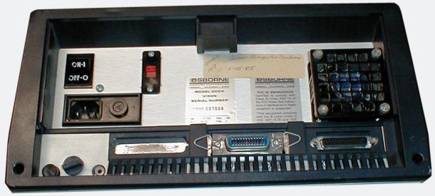 Rear panel
-
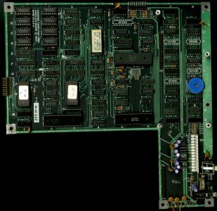 System board

Related pages
[edit | edit source]- Osborne Vixen Maintenance Guide
- Osborne Vixen Troubleshooting Guide
- Osborne Vixen Capacitor Replacement Guide
- Osborne 1
- Osborne Executive
References
[edit | edit source]- ↑ 1.0 1.1 1.2 Osborne Computer Corporation, The Osborne Vixen, sales brochure and order form, 4 pages, undated, hosted as File:Osborne Vixen Brochure.pdf.
- ↑ 2.0 2.1 2.2 Osborne Computer Corporation, Osborne 4 Theory of Operation Manual, Revision 1.0, part no. 2F40006-01, August 1985, corresponding to the revision C schematics, hosted as File:Osborne 4 Theory of Operation Manual Rev 1.0 1985.pdf. Section 1.1 (description and weight), 2.0 (system timing), 5.2 (ROM), 6.0 (dynamic RAM), 8.0 (I/O board), 9.0 (floppy disk control, Table 9-1, PDF page 54), 10.0 (display control).
- ↑ 3.0 3.1 3.2 3.3 Osborne Computer Corporation, Vixen Engineering Drawings, March 1983, hosted at Osborne Vixen Engineering Drawings Mar83. Detached List of Materials, VIXEN MAINLOGIC, LM# 6M00015-01, revision 2.1, 13 March 1983 (PDF pages 12 to 15); Detached List of Materials, VIXEN I/O, LM# 6M00016-01, revision 1.1, 13 March 1983 (PDF pages 27 and 28); monitor sub-assembly drawing (PDF page 2).
- ↑ Osborne Computer Corporation, Vixen schematic set, 13 sheets, hosted as File:Vixen Schematic.pdf. Sheet 1, power supply drawing (Astec, drawn 10 August 1983); sheet 2, Zenith monitor schematic 123-5657, issue A, revised 13 December 1982; sheets 3 to 13, logic drawings dated 1984.