

Sega 32X
 | |
| A Genesis 32X, the North American version | |
| Specifications | |
|---|---|
| Manufacturer | Sega Enterprises, Ltd. |
| Type | 32-bit add-on for the Mega Drive / Genesis |
| Released | 21 November 1994 (North America) November 1994 (Europe) 3 December 1994 (Japan)[1] |
| Discontinued | 1996[1] |
| Intro price | US$159.99, £169.99, ¥16,800[1] |
| CPU | Two 32-bit RISC SH2 (Hitachi HD6417095), 23 MHz, 20 MIPS each[2][3] |
| Memory | 2 Mbit SDRAM; 2 Mbit VRAM[2] |
| Storage | Its own cartridge slot, which also takes Mega Drive cartridges[1] |
| Display | 32,768 colours, through the console's video output[2] |
| Sound | PWM sound source, stereo[2] |
| Power | External AC adaptor, 10 V DC 850 mA (9 V on some PAL adaptors); about 4 W[2] |
| Dimensions | 115 × 210 × 100 mm[2] |
| OS / Firmware | — |
| Codename | Project Mars[1] |
The Sega 32X is a 32-bit add-on for the Mega Drive and Genesis, codenamed Project Mars, released in late 1994. It plugs into the console's cartridge slot, has two Hitachi SH2 processors and its own video display processor, plays its own cartridges and passes ordinary Mega Drive cartridges through to the console.[1][2] It was sold as the Super 32X in Japan and South Korea, the Genesis 32X in North America, the Mega 32X in Brazil and the Mega Drive 32X elsewhere.[1]
The 32X works only with a console. It needs its own power supply, a cable linking it to the console's video output, an extra conversion cable for the original model of the console, and two electromagnetic shield plates fitted into the console's cartridge slot.[1] The first Genesis 32X boards (VA0) also need an external Extension Unit.[4]
History
[edit | edit source]The 32X was released in North America on 21 November 1994 at US$159.99, in Europe the same month at £169.99, and in Japan on 3 December 1994 at ¥16,800. It was discontinued in 1996.[1]
Specifications
[edit | edit source]From Sega's service manual.[2]
| Item | Genesis 32X | Mega Drive 32X (PAL) | Mega Drive 32X (PAL G/I) |
|---|---|---|---|
| Adaptor input | AC 120 V, 60 Hz | AC 230 V, 50 Hz | AC 240 V, 50 Hz |
| Adaptor output | DC 10 V, 850 mA | DC 10 V, 850 mA | DC 9 V, 850 mA |
| Power consumption | About 4 W | ||
| Operating environment | 5 to 35 °C, 20 to 80 % RH, no condensation | ||
| Dimensions | 115 (W) × 210 (L) × 100 (H) mm | ||
| CPU | Master and slave 32-bit RISC SH2, 23 MHz, 20 MIPS | ||
| RAM | 2 Mbit SDRAM | ||
| VRAM | 2 Mbit | ||
| Sound | PWM sound source, stereo | ||
| VDP | Sega custom LSI | ||
| Colours | 32,768 | ||
| Video output | Composite video, RF, RGB | ||
Power
[edit | edit source]The 32X has its own DC jack, CN8, an EIAJ-3 type (Sega 212-5353), and its own adaptor; it is not powered from the console. Sega's adaptor for the Genesis 32X is 400-5135A (AC 120 V, DC 10 V 0.85 A); the PAL adaptors are 400-5208 (240 V, 10 V), 400-5209 (230 V, 10 V) and 400-5211 (240 V, 9 V).[3] The jack is the same part as on the Mega Drive II, and the Genesis II uses the same 400-5135A adaptor.[5]
The 32X and Mega Drive II supplies are centre positive. The Model 1 Mega Drive's DC input is wired sleeve positive, centre negative, so a Model 1 adaptor is the wrong supply for a 32X.[5][6] Check the output printed on the adaptor; Sega's own PAL adaptors are rated 10 V or 9 V.[3]
The 32X has no 7805 regulator. Its 5 V rail comes from IC13 on the sub board, an MC34063A or IR3M03AN switching regulator with choke L7, and IC10 on the main board is an RH5RL33A, a 3.3 V regulator.[3][7]
Boards
[edit | edit source]The 32X has a main board and a sub board, joined by two 40-pin flat cables (main board CN1 and CN2 to sub board CN4 and CN5).[3][8]
| Board | Parts |
|---|---|
| Main board | IC1 and IC2, the SH2 processors (HD6417095, Sega 315-0922, 315-0922A or, at IC2, 315-0998); IC3, 2 Mbit SDRAM (µPD4502161); IC4, the MARS interface (315-5818 gate array or 315-5818A standard cell array); IC5, the address selector (315-5805); IC6, the VDP (315-5781 or 315-5781A); IC7 and IC8, 1 Mbit DRAM (TC511664BJ-80 or LC321664); IC9, 74AC04; IC10, RH5RL33A; CE1 and CE2, 47 µF 10 V tantalum chips (153-0119) |
| Sub board | IC11, sound network and headphone amplifier (BA6166FS, 315-5684); IC12, video mix (BA7237FS, 315-5788); IC13, switching regulator; IC14, PST993E reset IC; IC15, 74HC74; IC16, 74LS00; L7, choke; X1, 3.579545 MHz crystal; CN3, 64-pin edge connector; CN6 and CN7, 9-pin mini-DIN AV connectors; CN8, DC jack; CE3 to CE20, the electrolytics |
| Assembly | Description | Main board | Sub board | Region |
|---|---|---|---|---|
| 837-10924 | IC BD MARS VA0 NTSC | 837-10925 | 837-10926 | USA and Canada, VA0 |
| 837-11292-01 | IC BD MARS VA1 NTSC | 837-11293-01 | 837-10926 | USA and Canada, VA1 |
| 837-11294-01 | IC BD MARS VA1 PAL | 837-11293-01 | 837-10928-01 | PAL G/I |
| 837-11533 | IC BD MARS VA1 ASIA NTSC | 837-11534 | 837-10928-01 | Asia |
Sega integrated the Extension Unit circuit on the main board of the Genesis 32X VA1, so only the VA0 needs the external Extension Unit; the Mega Drive 32X had the circuit built in from the first unit.[4]
Accessories
[edit | edit source]Sega's accessories list: connector cable, conversion cable, mono audio/video cable, spacer for the Genesis II / Mega Drive II, AC adaptor, electromagnetic shield plates, RF unit (PAL versions except France), mono Scart cable (France only), and the Extension Unit (Genesis 32X VA0 only).[4] The two shield plates fit into the console's cartridge slot as part of the installation.[1]
Use with a Model 1 console
[edit | edit source]Sega's service bulletins record lock-ups and screen shake when the 32X is used with some Model 1 Mega Drive boards, and fix them on the console. Bulletin 008 (December 1994) changes C92, removes FB7 and C112 and adds a ground jumper on the VA4 board; bulletin 012 (March 1995) removes C78 and C100 on the VA4; bulletin 014 (April 1995) removes C78 and adds a jumper from IC1 pin 15 on VA6.0, 6.5 and 6.8 boards. Bulletin 011 (March 1995) adds C96 and C97 to 32X boards with the standard cell array version of IC4.[9] The modifications are described on the Sega 32X Maintenance Guide.
Adjustment
[edit | edit source]The only adjustment in Sega's manual is the video frequency match: with the 32X removed from the console and its covers off, apply 5 V to IC14 pin 1 and to IC12 pin 31 (test mode), and adjust trimmer C72 for 3.579545 MHz ± 10 Hz at IC12 pin 20.[10]
Documentation
[edit | edit source]- Sega Genesis 32X / Mega Drive 32X Service Manual: No. 012, June 1995, with schematics, parts specifications and the full parts lists.
- Sega 32X Service Bulletins: bulletins 008, 011, 012 and 014.
Gallery
[edit | edit source]-
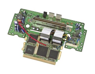 Genesis 32X boards: the sub board (top) with the cartridge slot and AV and DC connectors, and the main board (bottom) with the SH2s, the VDP and the edge connector to the console, joined by the two flat cables
-
 Sega's circuit board diagram for the 32X sub board


Related pages
[edit | edit source]- Sega 32X Maintenance Guide
- Sega 32X Troubleshooting Guide
- Sega 32X Capacitor Replacement Guide
- Sega Mega Drive / Genesis (Model 1)
- Sega Mega Drive / Genesis (Model 2)
- Sega CD (Model 2)
References
[edit | edit source]- ↑ 1.00 1.01 1.02 1.03 1.04 1.05 1.06 1.07 1.08 1.09 32X—link(accessed 2026-10-01) Secondary source; the dates and prices are cited there to Sega's Japanese 32X pages, Kent's The Ultimate History of Video Games (2001), p. 493, and Retro Gamer.
- ↑ 2.0 2.1 2.2 2.3 2.4 2.5 2.6 2.7 Sega Enterprises, Ltd., Service Manual, Genesis 32X (VA0, VA1) / Mega Drive 32X, No. 012, June 1995, section 1, specifications, p. 2. See Sega Genesis 32X / Mega Drive 32X Service Manual.
- ↑ 3.0 3.1 3.2 3.3 3.4 3.5 3.6 Sega Enterprises, Ltd., Service Manual, Genesis 32X (VA0, VA1) / Mega Drive 32X, No. 012, June 1995, section 9, exploded view and parts lists, pp. 34-38 (PDF pp. 28-33). See Sega Genesis 32X / Mega Drive 32X Service Manual.
- ↑ 4.0 4.1 4.2 Sega Enterprises, Ltd., Service Manual, Genesis 32X (VA0, VA1) / Mega Drive 32X, No. 012, June 1995, "Before referring to the service manual" and section 3, accessories, pp. 2-3. See Sega Genesis 32X / Mega Drive 32X Service Manual.
- ↑ 5.0 5.1 Sega Enterprises, Ltd., Service Manual, Genesis II / Mega Drive II (PAL-B/I/G, RGB), No. 001, June 1993: schematic (DC input at CN7, centre pin positive), electrical parts list (CN7, 212-5353) and accessories lists (400-5135A, AC 120 V / DC 10 V 0.85 A). See Sega Service Manual - Genesis II / Mega Drive II - June 1993.
- ↑ Sega Enterprises, Ltd., Mega Drive Maintenance Manual, PAL-G, August 1992, Rev. A, section 9, schematic diagrams for PC BD M5 PAL-G VA4 main (PDF pp. 64-68): the DC jack sleeve goes through FB1 and the power switch to IC15 (7805), and the centre pin through FB2 to ground. See Mega Drive Maintenance Manual - PAL-G, August, 1992, Rev. A.
- ↑ 32X—link(accessed 2026-10-01) Secondary source: IC list and capacitor list for the 837-10925 main board and 837-10926 sub board.
- ↑ Sega Enterprises, Ltd., Service Manual, Genesis 32X (VA0, VA1) / Mega Drive 32X, No. 012, June 1995, section 4, disassembly, p. 4. See Sega Genesis 32X / Mega Drive 32X Service Manual.
- ↑ Sega Quality Assurance Division, service bulletins 008 (13 December 1994), 011 (16 March 1995), 012 (28 March 1995) and 014 (12 April 1995). See Sega 32X Service Bulletins.
- ↑ Sega Enterprises, Ltd., Service Manual, Genesis 32X (VA0, VA1) / Mega Drive 32X, No. 012, June 1995, section 5, adjustment, p. 5. See Sega Genesis 32X / Mega Drive 32X Service Manual.