

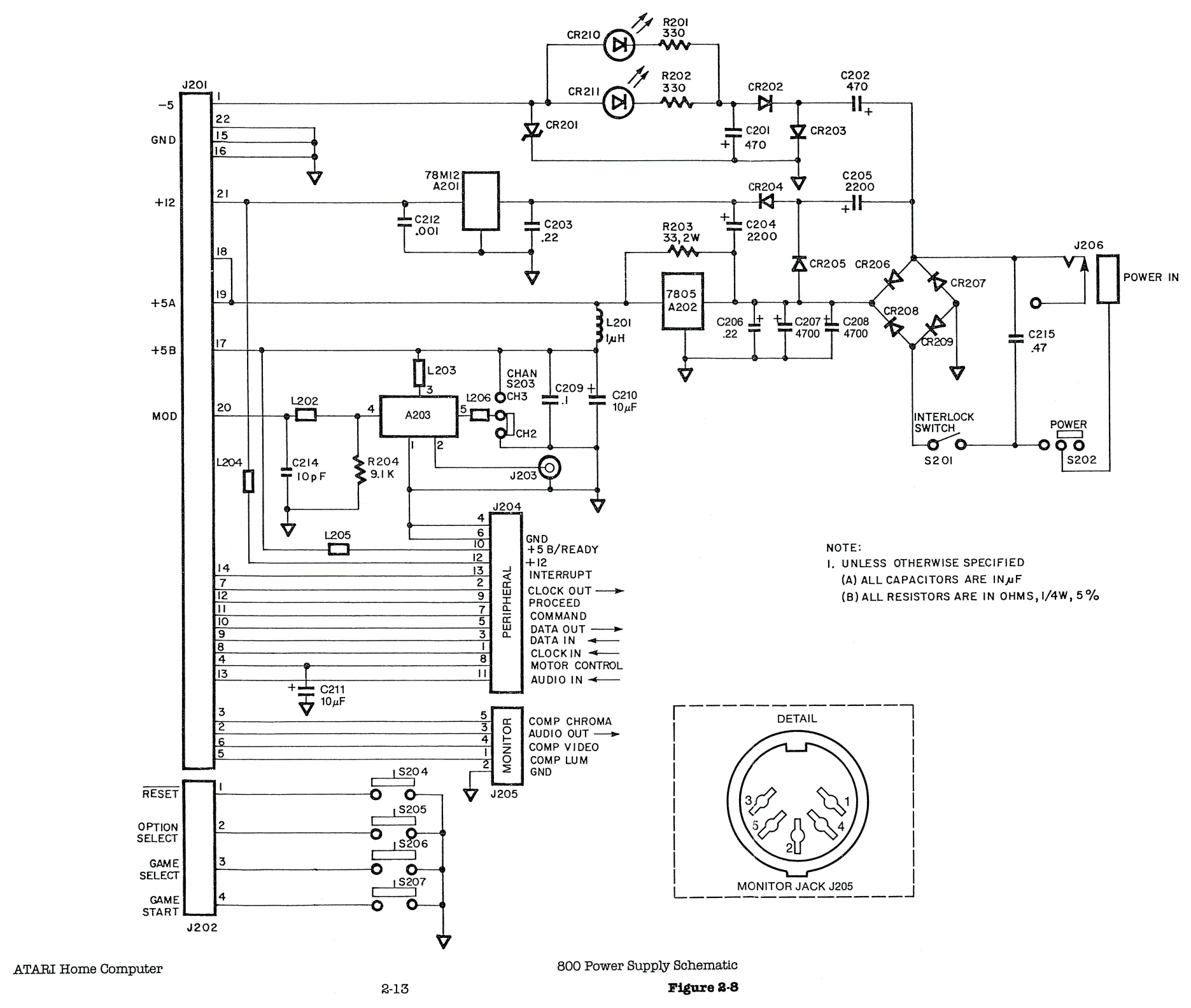
File:Atari 800 power supply schematic (Field Service Manual figure 2-8).png

Summary
[edit | edit source]

Figure 2-8 of Atari's 400/800 field service manual: the Atari 800 power supply board. 9 V AC enters at J206 through the power switch S202 and the interlock switch S201 to the bridge CR206 to CR209; the 7805 regulator A202 with the 33 Ω 2 W resistor R203 across it makes +5 V, the doubler CR204 and CR205 with the 78M12 regulator A201 makes +12 V, and CR202, CR203 and the zener CR201 make −5 V, with the two LEDs CR210 and CR211. Outputs go to the motherboard through J201; the board also carries the RF modulator A203, the peripheral (SIO) socket J204, the monitor socket J205 and the console keys S204 to S207.
Source
[edit | edit source]

Rendered from Atari 400 800 Field Service Manual, May 1983 on the Internet Archive (Atari, Inc., ATARI Home Computer Field Service Manual 400/800, May 1983 revision), PDF page 51, at 150 dpi and cropped. The June 1982 edition is hosted here as Atari 400 800 Field Service Manual June 82.
Author
[edit | edit source]

Atari, Inc.
Licence
[edit | edit source]

Copyright Atari, Inc. Hosted for preservation and repair reference, with the source cited.
File history
Click on a date/time to view the file as it appeared at that time.
| Date/Time | Thumbnail | Dimensions | User | Comment | |
|---|---|---|---|---|---|
| current | 12:38, 25 October 2026 | | 1,871 × 1,585 (854 KB) | Josh (talk | contribs) | Upload figure for Atari 400 and 800 repair guides |
You cannot overwrite this file.
File usage
The following 3 pages use this file:
