

File:Panasonic FS-A1WX power supply circuit (figure 8).png

Summary
[edit | edit source]

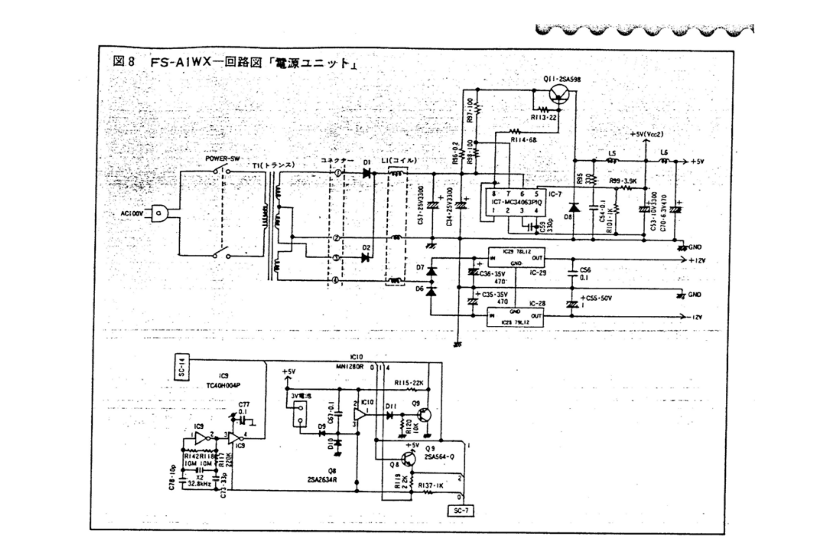
Figure 8, "FS-A1WX circuit diagram: power unit", from page 63 of the scanned FS-A1WX circuit pages: the double-pole power switch and transformer T1, the four-pin connector to the main board, rectifiers D1 and D2 with reservoir capacitors C57 and C34 (25 V, 3300 µF), the MC34063 DC/DC converter IC7 with switching transistor Q11 (printed "2SA598"; the BABAX parts list gives 2SA1598), current-sense resistor R96 (0.2 Ω), feedback resistors R99 (3.9 kΩ) and R101 (1 kΩ), output capacitor C53 (10 V, 3300 µF), inductors L5 and L6 and C70 (6.3 V, 470 µF) on the +5 V line; D7 and D6 with C36 and C35 (35 V, 470 µF) feeding the 78L12 (IC29) and 79L12 (IC28) regulators for +12 V and −12 V; and below them the reset IC10 (MN1280R), the 3 V backup battery connection, the clock oscillator (IC9, X2 32.8 kHz) and the backup switching transistors Q8 and Q9. Rendered from File:Panasonic FS-A1WX circuit diagrams (pages 55 to 64).pdf, PDF page 7.
Source
[edit | edit source]

Internet Archive item "Panasonic FS-A1WX Service Manual (JP)", https://archive.org/details/panasonicsa1wxsm (retrieved 2026-10-21). Scanned by Jipe, converted to PDF by HansO, 2009.
Author
[edit | edit source]

Matsushita Electric Industrial Co., Ltd. (Panasonic), as credited by the Internet Archive item.
Licence
[edit | edit source]

Copyright of the original publisher. Hosted for repair reference, with the source cited.
File history
Click on a date/time to view the file as it appeared at that time.
| Date/Time | Thumbnail | Dimensions | User | Comment | |
|---|---|---|---|---|---|
| current | 14:38, 21 October 2026 | | 2,924 × 1,880 (671 KB) | Josh (talk | contribs) | Upload for the FS-A1WX and FS-A1WSX pages; source and licence on the file page |
You cannot overwrite this file.
File usage
The following 8 pages use this file:
