
IBM PC AT (5170) Battery Replacement

The IBM PC AT (5170) keeps its SETUP configuration and the time in a Motorola MC146818 real-time clock and CMOS RAM chip. When the machine is off, that chip runs from a battery plugged into connector J21 on the system board.[1][2] IBM supplied a 6 V lithium battery, part number 8286121, attached to the back panel of the system unit by a plastic attaching strip; early batteries may also be held by two screws.[3][4][5] IBM no longer sells it, and old replacement stock found for sale is possibly well depleted.[5]
Fitting a new battery does not clear the configuration error by itself: the error stays until SETUP has been completed.[6][5]
Symptoms
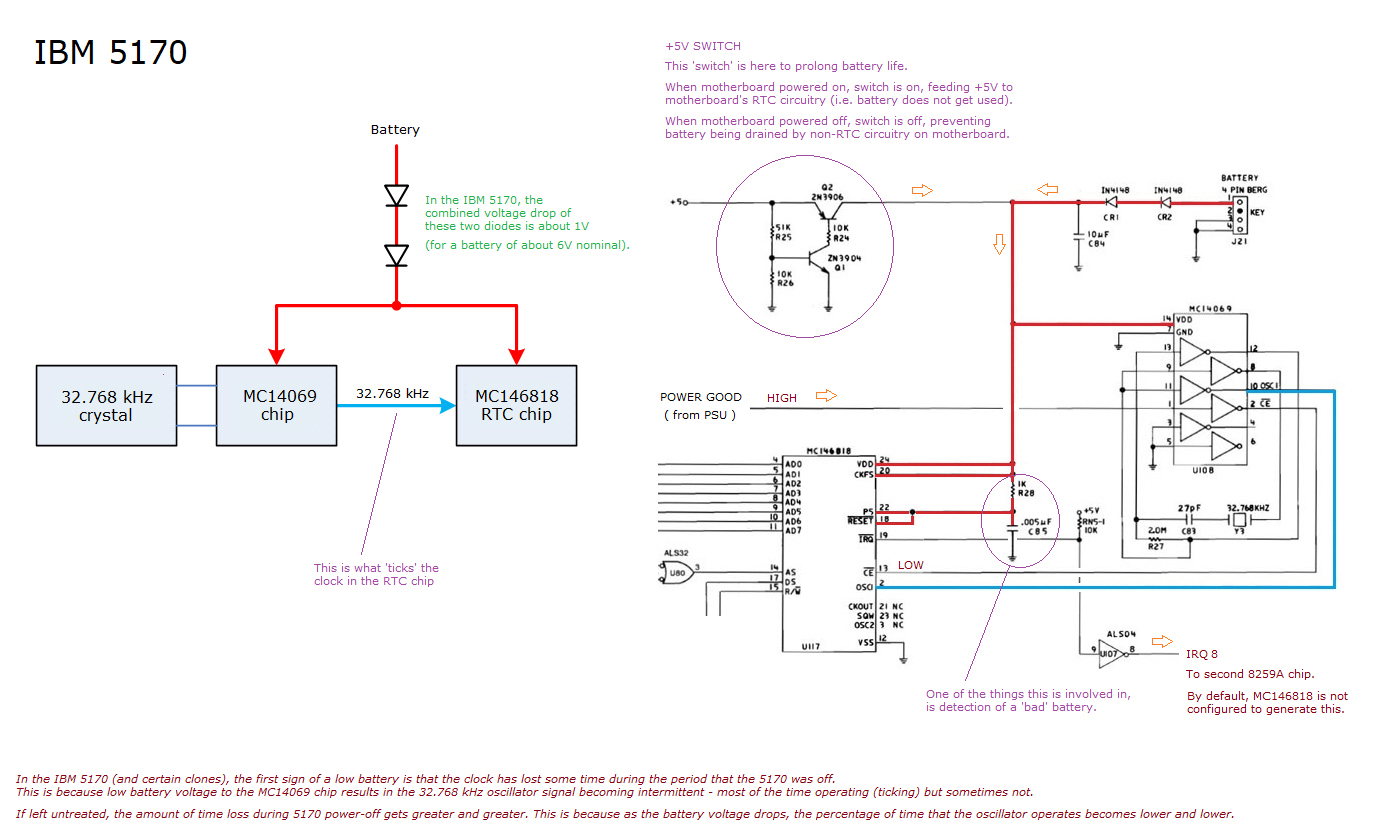
[edit | edit source]- The configuration survives power-off but the clock loses time while the machine is off, and loses more as the weeks go by. Minuszerodegrees gives this as the first sign of a low battery: the MC14069 that drives the clock's 32.768 kHz crystal starts to run only part of the time as its supply falls.[5][7]
- POST error 161, "System Options Not Set", which IBM's BIOS uses for a dead battery. Minuszerodegrees has seen boards that do not detect a dead battery and show 162 instead.[8][9]
- 161 on the first power-on after a battery has been fitted. IBM expects this; run SETUP.[6]
A clock that will not keep time with a good battery, and 162 or 163 errors with other causes (a video card that does not match SETUP, a SETUP that was started and not finished), are covered in the maintenance guide and the IBM PC AT Troubleshooting Guide.
Safety
[edit | edit source]IBM's caution for this battery: it presents a fire, explosion and severe burn risk. Do not recharge it, remove its polarised connector, take it apart, heat it above 100 °C, burn it or expose the contents of the cells to water.[3] The 1984 service manual adds: do not solder directly to the cell.[10] If a battery has leaked, see Battery Explosion, Capacitor or Corrosion Damage.
The procedure below is done with the power cord unplugged from the outlet.[11]
Tools and parts
[edit | edit source]- The system unit key, to unlock the cover. If the key is lost, IBM's way of releasing a locked cover is on the main IBM PC AT page.[11]
- A screwdriver or nut driver for the five cover mounting screws; IBM's drawing shows hexagon-headed screws with a slot.[11]
- A multimeter with a 12 V DC range.[6]
- IBM's Diagnostics for the IBM Personal Computer AT diskette (or the Advanced Diagnostics), or one of the other ways of running SETUP listed below.[12]
- A replacement battery from the table below.
| Battery | Nominal voltage | Notes |
|---|---|---|
| IBM 8286121 or a third-party equivalent | 6 V | Lithium. The battery pictured by minuszerodegrees has a resistor on top; a replacement does not need one. Minuszerodegrees shows a Tadiran TL-5293W as an example of a third-party replacement; batteries like it found for sale are possibly well depleted. |
| Four AA cells in a holder | 6 V | Needs a holder with the right connector, or the connector moved across from the old battery. In February 2026 minuszerodegrees found Jameco selling a ReliaPro four-AA holder with a wired 4-pin connector (Jameco item 105858). |
| CR-P2 lithium cell in a holder | 6 V | Needs soldering: move the leads and connector across from the old battery. |
| Three AA cells in a holder | 4.5 V | As for four cells. |
| 3.6 V lithium, such as Tadiran TL-5242W, which has the right connector | 3.6 V | Borderline. Some boards keep their settings on it but lose time. |
Do not fit a rechargeable battery: the system board has no charging circuit. Do not fit anything above 6 V nominal (see below).[5]
How the battery circuit works
[edit | edit source]
On IBM's drawing, the battery on J21 reaches the clock supply through two 1N4148 diodes, CR2 and CR1. C84 (10 µF) sits on that supply, which feeds VDD (pin 24) of the MC146818 and VDD (pin 14) of U108, the MC14069 that runs the 32.768 kHz crystal Y3. Transistors Q2 (2N3906) and Q1 (2N3904) connect +5 V to the same supply.[13] Minuszerodegrees explains the transistors as a switch: when the board is powered, +5 V feeds the clock and the battery is not used; when it is off, the switch opens so the rest of the board cannot drain the battery.[7]
Minuszerodegrees measured about 1 V across CR1 and CR2 together on several unpowered boards with a 6 V battery, and about 0.8 V with a 3.6 V battery. The MC146818 datasheet gives 3 V to 6 V operation and the MC14069 3 V to 18 V.[5][14] So a battery measuring over 7 V takes the MC146818 past its rating, which is why minuszerodegrees advises nothing above 6 V nominal; a new 6 V lithium battery measures a little over 6 V. Feeding three boards from a regulated supply in place of the battery, minuszerodegrees found that they began to lose time at supply voltages of 3.6 to 3.7 V.[5][14]
The J21 pin numbers
[edit | edit source]IBM's documents number J21 in two ways. The connector table in the Technical Reference numbers the pins 1 to 4 from the right of the system, with pin 1 ground, pin 2 not used, pin 3 the key and pin 4 6 V DC.[2] The logic diagram draws pin 1 to the diodes, pin 2 as the key and pins 3 and 4 to ground.[13] IBM's battery check in the service manual puts the meter's common lead on pin 1 and the voltage lead on pin 4 of the battery connector.[6] Both agree that the battery sits across the two end pins of the four. Work from the plug of the original battery and from a meter, not from the pin numbers.
Procedure
[edit | edit source]Removing the cover
[edit | edit source]
IBM's procedure:[11]
- Switch off the system unit.
- Unplug the power cord from the outlet.
- Move all external options away from the system unit. The 1984 manual also has you switch off all external devices and disconnect all cables from the system unit at this point.[15]
- Turn the key to the unlocked position and remove it.
- Turn the system unit round so that its rear faces you.
- Remove the plastic back panel from the rear of the system unit. It is held on by plastic fastener strips.
- Remove the five cover mounting screws.
- Slide the cover forward, away from the rear panel, until it is clear of the system unit.
Finding the battery and J21
[edit | edit source]
On both the type 1 and type 2 boards, IBM's location drawings put the battery connector next to the keyboard connector at the rear of the board, and the Technical Reference layout drawing shows J21 there too.[16][2] In IBM's removal drawing the battery is fixed to the back panel at the end beyond the adapter slots, above the connector.[3]

Testing the old battery
[edit | edit source]IBM's check, from the 1989 service manual:[6]
- With the system unit off and the cover removed, disconnect the battery from the system board. A battery measured while it is connected gives readings that vary with the board's drain.
- Set the meter to its 12 V DC range. Put the common lead on pin 1 and the voltage lead on pin 4 of the battery connector.
- Look for at least 6.0 V DC. Below that, replace the battery.
Note which end of the plug is positive before going further. A replacement must have its positive lead at the same end.[5]
Removing the old battery
[edit | edit source]
- Disconnect the battery cable from J21 on the system board, if it is not already off.[3]
- Pull the battery gently away from the back panel to free it from the attaching strip, and lift it out of the system unit.[3]
- If the battery is also held by two screws, as early ones were, remove them. IBM says they are no longer needed.[3]
Preparing a replacement
[edit | edit source]
- A four-AA holder sold without a connector can take the connector from the old battery, or a new connector and pins. Minuszerodegrees suggests crimping the pins on with pliers, which is good enough for the very small current the clock draws, or using single-post connectors.[5] For the general method see Connector Pin Replacement and Crimping.
- For a CR-P2 cell, solder the old battery's leads and connector to the holder's tabs, observing polarity, and cover the tabs with heat-shrink tubing in case the holder falls from the case onto the system board.[5]
- Measure the finished pack at its plug. Check that the positive lead is at the same end as on the old battery, and do not fit a pack that measures over 7 V.[5]
Fitting the new battery
[edit | edit source]IBM's replacement procedure, from the 1984 service manual:[10]
- Line the battery's attaching strip up with its mounting position on the back panel, and press the battery on to secure it. Fix a battery holder so that it cannot fall onto the system board.[5]
- Connect the battery cable to J21.
- Refit the cover: slide it towards the rear of the system unit, line the five screws up with the threaded tabs and tighten them, refit the back panel and reconnect the cables.[17]
- Run SETUP.
Running SETUP
[edit | edit source]IBM's SETUP program is on the Advanced Diagnostics diskette. Before running it, IBM lists the option adapters fitted, reads the fixed disk drive types from the labels on the drives, and reads the diskette drive types from the bezels: a double-sided (360 KB) drive has an asterisk on its bezel and a high-capacity drive has none.[18] In SETUP, IBM's 20 MB fixed disk is type 2 and its 30 MB fixed disk type 20.[19]
Minuszerodegrees' procedure with the Diagnostics for the IBM Personal Computer AT diskette, starting from a machine showing 161, 162 or 163:[20]
- Put the diskette in drive A: and restart the machine. At the "(RESUME = "F1" KEY)" prompt, press F1, and the machine boots from the diskette.
- At "Have you completed running this program since connecting the battery?", type N and press Enter. In IBM's description of this menu, answering Y makes the program report "151 Error - Battery Defective".[21]
- Enter the date and the time in the formats shown, then confirm them with Y and Enter.
- At the prompt to locate the setup foldout in the Installation and Setup manual, press Enter.
- Confirm the diskette drive types with Y and Enter.
- Enter the number of fixed disks (0, 1 or 2) and, for each, its type number, and confirm.
- Confirm the primary display, the base memory and the expansion memory with Y and Enter. Minuszerodegrees finds the program's own memory figures reliable.
- Confirm the summary of options with Y and Enter, remove the diskette and press Enter. The machine restarts.
Without the diskette, SETUP can be run from Cassette BASIC with a program generated on a modern PC, or with the third-party GSETUP program booted from a diskette in a temporarily fitted 1.44 MB drive. Minuszerodegrees gives both procedures. All three methods assume IBM BIOS ROMs.[12][8]
Testing
[edit | edit source]- The machine starts without 161, 162 or 163, and keeps its configuration when switched off and on again.[6][5]
- Switch off for at least an hour, then check the time. Minuszerodegrees used about an hour off in its tests of low battery voltage; a clock that has lost time points to too low a supply at the clock chips.[14][5]
- To check the supply at the chip, measure with the machine off between VDD (pin 24) and VSS (pin 12) of the MC146818 on IBM's drawing. Expect the battery voltage less about 1 V for a 6 V battery, and not below the 3 V minimum of the datasheet.[13][5]
- If the clock still loses time with a good supply at the chip, see the maintenance guide: minuszerodegrees' failure history records faulty MC146818 chips on type 1 boards.[22]
Related pages
[edit | edit source]- IBM PC AT (5170)
- IBM PC AT Maintenance Guide
- IBM PC AT Troubleshooting Guide
- IBM PC AT Capacitor Replacement Guide
- IBM PC AT 5170 Technical Reference (September 1985)
- IBM Personal Computer Family Service Information Manual
- Battery Explosion, Capacitor or Corrosion Damage
- Connector Pin Replacement and Crimping
References
[edit | edit source]- ↑ IBM, Technical Reference, Personal Computer AT, First Edition (September 1985), Section 1, "Real-Time Clock/CMOS RAM Information", p. 1-56. Hosted as File:IBM PC AT 5170 Technical Reference Sep85.pdf, described at IBM PC AT 5170 Technical Reference (September 1985).
- ↑ 2.0 2.1 2.2 IBM, Technical Reference, Personal Computer AT (September 1985), "Connectors": battery connector J21 pin assignments, p. 1-72; system board layout drawing with the battery connector (J21) beside the keyboard connector, p. 1-74.
- ↑ 3.0 3.1 3.2 3.3 3.4 3.5 IBM, Hardware Maintenance Reference, 6280088 (1986), Repair Information (AT), "Battery 1010", p. 3-29: the removal steps, the early two-screw mounting, and the lithium battery caution.
- ↑ IBM, Hardware Maintenance Service, 6280087, Revised Edition (March 1986), "Parts (AT)", Assembly 2 "System Unit – Interior (5170)", p. 9: battery FRU 8286121. Hosted as File:IBM Hardware Maintenance Service 6280087 Parts Catalog (AT).pdf.
- ↑ 5.00 5.01 5.02 5.03 5.04 5.05 5.06 5.07 5.08 5.09 5.10 5.11 5.12 5.13 5.14 5.15 Minuszerodegrees.net, "IBM 5170 – Battery": J21, the IBM 6 V lithium battery 8286121, third-party replacements, the four-AA, three-AA, CR-P2 and 3.6 V options, polarity and heat-shrink notes, the 1 V drop across CR1 and CR2, the MC146818 3 V to 6 V rating, and the advice against more than 6 V nominal.
- ↑ 6.0 6.1 6.2 6.3 6.4 6.5 IBM, IBM Personal Computer Family Service Information Manual, SA38-0037-00 (July 1989), Chapter 9, "Battery Voltage", p. 9-9, and Figure 9-19: disconnecting the battery, the 12 V DC range, pins 1 and 4, the 6.0 V minimum, and the 161 message after a new battery. Hosted as File:IBM Personal Computer Family Service Information Manual SA38-0037-00.pdf, described at IBM Personal Computer Family Service Information Manual.
- ↑ 7.0 7.1 Minuszerodegrees.net, IBM 5170 battery circuitry diagram, annotated copy of IBM's schematic: the +5 V switch and why a low battery makes the clock lose time.
- ↑ 8.0 8.1 Minuszerodegrees.net, "IBM 5170 – Performing SETUP Using BASIC Code": boards that show 162 instead of 161 for a dead battery, and SETUP from Cassette BASIC.
- ↑ Minuszerodegrees.net, "IBM 5170 – POST – Some errors (on-screen, and otherwise)": 161 "System Options Not Set" (dead battery).
- ↑ 10.0 10.1 IBM, Hardware Maintenance and Service, 1502242 (March 1984), Volume 2, "Battery Removal 1030", p. 5-29, and "Battery Replacement 1031", p. 5-30, with the caution against soldering directly to the cell.
- ↑ 11.0 11.1 11.2 11.3 IBM, Hardware Maintenance Reference, 6280088 (1986), Repair Information (AT), "Cover 1005", pp. 3-27 and 3-28. Hosted as File:IBM Hardware Maintenance Reference 6280088 Repair Information (AT).pdf.
- ↑ 12.0 12.1 Minuszerodegrees.net, "IBM 5170 – SETUP Procedure": the diagnostics diskette, Cassette BASIC and GSETUP methods, all assuming IBM BIOS ROMs.
- ↑ 13.0 13.1 13.2 IBM, Technical Reference, Personal Computer AT (September 1985), "Type 2 512KB Planar (Sheet 17 of 21)", p. 1-114 (PDF page 130): J21, CR1, CR2, C84, Q1, Q2, R24 to R26, U108 and the MC146818.
- ↑ 14.0 14.1 14.2 Minuszerodegrees.net ('modem7'), "Using a 3.6 Volt Battery in an IBM 5170", June 2010: measurements on three boards of the battery voltage at which time loss began after about an hour off, the 0.8 V drop across CR1 and CR2, and the MC14069 supply range.
- ↑ IBM, Hardware Maintenance and Service, IBM Personal Computer AT, 1502242 (March 1984), Volume 2, "Cover Removal 1005", pp. 5-7 and 5-8. Scan via minuszerodegrees.net.
- ↑ IBM, Hardware Maintenance Reference, 6280088 (1986), Repair Information (AT), "Locations": System Board Type 1, p. 3-11, and System Board Type 2, p. 3-12.
- ↑ IBM, Hardware Maintenance and Service, 1502242 (March 1984), Volume 2, "Cover Replacement 1006", p. 5-9.
- ↑ IBM, Hardware Maintenance and Service, 1502242, Volume 2, Section 6, "System Setup", pp. 6-3 and 6-4 (supplement page dated 30 September 1985).
- ↑ IBM, IBM Personal Computer Family Service Information Manual, SA38-0037-00, Chapter 9, fixed disk types, p. 9-7.
- ↑ Minuszerodegrees.net, "IBM 5170 – Performing SETUP Using The 'Diagnostics for the IBM Personal Computer AT' Floppy", steps 1 to 17.
- ↑ IBM, Hardware Maintenance Reference, 6280088 (1986), Introduction to Diagnostics (AT), "Battery Defective Menu", p. 2-9. Hosted as File:IBM Hardware Maintenance Reference 6280088 Introduction to Diagnostics (AT).pdf.
- ↑ Minuszerodegrees.net, "Some history of IBM 5150/5155/5160/5170 motherboard failure": three faulty MC146818 chips, all on type 1 boards.